

Introduction: Word Clock Using Arduino and RTC


I decided to make a special gift for my girlfriend for her birthday. As we're both into electronics, it was quite a good idea to make something "electronicsy". Besides, we both have gifted each other this kind of self made gifts before, and it just feels awesome.
So, I was just surfing YouTube and I came across a video. After watching that, I was pretty sure that I am going to make this. That's how it all started.
I researched the internet for more that kind of tutorials, but nothing suited my needs. My requirements were:
1. Easy construction of housing for all the parts to keep in.
2. The controller used must be Arduino.
3. For time keeping a Real Time Clock must be used.
4. The LEDs used must be WS2812B.
I watched several tutorials, and decided to merge them in order to create a word clock according to my requirements. There are many word clock tutorials in the internet, and I decided to share my creation because none of them is of this kind. Also it's easy to build an money friendly.
The tutorials I referred to are listed below.
2. Jeremy Blum
3. Scott Bezek
So, let's get started.
Step 1: Parts Required


Electronics:
Arduino (better if smaller version like pro mini)
Neopixel LED (WS2812B) (better if in strip form, I used 30 leds/m version)
Real Time Clock (DS3231)
10k Potentiometer
5V 2A power supplly
Tools:
Access to carpentry tools (if you are about to make the wooden box yourself)
Soldering Tools
0.75 square mm solid wire
Jumper wires
White cardboard
Hardboard
Hot glue
Paper glue
Hammer and nails
Ruler
Utility knife
Printer (able to print in transparency sheet, or you can just get it printed from a shop)
Double sided tape
Super glue
Butter paper (2 nos.) (or any color diffuser you like)
Red hand made paper
Wire stripper and nipper
Glass
Softwares:
Inkscape
Arduino IDE
Adafruit NeoPixel Library
Step 2: The Wooden Box


At first, I decided to make a 7 x 7 inch box with viewing area of 6 x 6 inch, but soon I realized the vinyl will be too small for all the Leds to fit in, so I had to increase the viewing area (size of vinyl) to 8 x 8 inch. That made me to increase the box size to 9 x 9 inch. I also wanted a door in the back.
I have no carpentry tools or any experience in carpentry. So I went to a nearby carpentry and ask him to made a box with all my specifications. He built it perfectly. After that, to make it look good I asked him to add my choice of wood laminate (wood veneer). If you're also adding a wood veneer, use something dark, it will make the Leds look more bright and good. Or you can use a wood finish. It's totally up to you, after all it's your design. Also, the carpenter said that he will not be able to add wood veneer in the lip, because it's too thin. So after some failed ideas, a friend suggested me to download any good looking veneer from the internet and print it, and then stick it using paper glue. I followed him and instead of downloading one from the internet, I scanned the same veneer used in the box from my scanner and printed it. Problem solved!
After the box was complete, I brought it home, and marked positions for potentiometer and DC barrel jack. I took it back and asked him to make holes at that positions. At this point the box is complete.
Step 3: The Vinyl


I don't have any laser cutter or craft cutter. So I decided to go with the idea of printing the vinyl in transparent sheets. I made the vinyl in Inkscape. As said before, the size is 8 x 8 inch. You can download the fonts I used from Jeremy Blum's site, link is provided in the introduction. I didn't want to take any risk, so instead of printing it myself, I went to a nearby printing store and get it printed there. One sheet wasn't enough to block all the lights, so I used two sheets and overlapped them. I used super glue to stick them together.
Now I cut 4 strips of red hand made paper into size 9 x 1 inch and stick it using double sided tape in the four corners of the vinyl. The size of vinyl is now 9 x 9 inch. After that, put the vinyl in the box to check if it fits. If it does not fit make some adjustments and fit it perfectly
After that is done, I took two butter paper, stacked it one above another and stick it using paper glue. When it's dry, it glued it behind the vinyl using super glue.
The vinyl is done now.
Attachments

Step 4: The Code: Part 1
I started coding from scratch. Understanding the code is a vital part of this project because half of the project depends solely on it. I'll try to explain what I did in my code.
First of all, to make my life easier, I divided the neopixels in two strips. It makes the coding easier. One strip is connected to pin 9 and controls the words "Sneha, I, <heart>, YOU". The rest are connected to pin 8.
Go to this site and understand how to work with DS3231. Instead of using a RTC library, I used the code for DS3231 from that site only, as it's easy to work with and takes less space in the microcontroller.
http://tronixstuff.com/2014/12/01/tutorial-using-d...
Now you know after calling the function readDS3231time(), you'll have the values of seconds, minutes, hours, weekday, month, year in their respective variables.
Learn how to use neoPixel library from this site:
https://learn.adafruit.com/adafruit-neopixel-uberg...
Now, what I did was I created a function that adjusts the brightness of the LEDs using a 10k potentiometer. It is pretty easy and every one should be able to understand it. The pot is connected to pin A0.
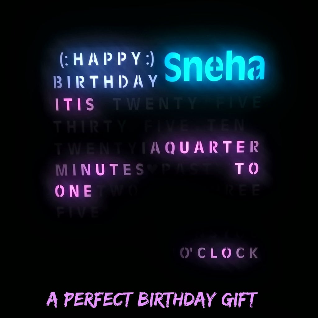
After that I created a function that checks if it's her birthday by calling readDS3231time() function and comparing "dayOfMonth" & "month" with her birth date and birth month. If this condition satisfies, micro controller should light "HAPPY BIRTHDAY" with white color.
The neopixel WS2812B is able to emit 65 million colors, and using only 3 or 4 colors was not doing justice to it. So, I decided that the color of word "Sneha" will change every hour and that of the rest will change every 6 hours. That requires RGB codes of 28 different colors, which I found from the internet. To store it, I used 2-D array which you can see in the very start of the program. I also arranged it in such a manner that two color codes with most blues or most reds or most greens are not adjacent to each other. Otherwise the change in color will be unnoticeable. Starting 24 colors are for word Sneha and rest 4 are for time showing. So, I made a 28 x 3 array and loaded it with the color codes.
Step 5: The Code: Part 2
Now, I created a function to apply color only to the word "Sneha". It works in this way:
If hour is 1 it should take color codes from color[1] of the 2D array, if hour is 13, color codes should be taken from color[13]. So I just used the variable "hour" for choosing the color. Further, int he "for" loop, if "i" is 0 the value coming from the array is value of red color, if "i" is 1 its value of green and if 2 its blue. Using this tactic, "Sneha" changes it's color every hour.
The function glowTime() handles the task of showing time.
First of all, if you light a Led then after going to the next led, you should turn it off, otherwise it's values will be floating and the led will show random colors. The time in the word clock changes every five minutes. So I checked if "minute" is completely divisible by 5 and to do it only once, I also checked if "second" is 1. If this condition satisfies, then turn off all the led.
After that I used the same tactic for choosing colors as I used In the word "Sneha" using some variables to hold values of colors (red, green & blue).
After that I just compared "minute" with different number that shows the number of minutes and used it to assign the number which is the numbering of LED. You'll notice I've used two variables here as there are some words that uses two LEDs. Where there is only one LED needed to glow, I assigned the second variable to number 27. And as there are no number 27 Led, nothing will be lit.
Same logic is used ith "hour" and deciding if it's "past" or "to". At the end, light up all the Leds using the variables to which numbers are assigned which led we have to turn on.
At last, in the loop(), what I did is I checked if it's 12 O'clock in the morning. If it's so the "Sneha, I, <heart> , YOU" will light up for three seconds. This way you say her I love you everyday without forgetting ;). And if it's not 12 o'clock call all the functions and let them do their job.
The sketch is attached in this step. It is well commented, and should not be hard for anyone to understand.
Attachments

Step 6: The Circuit Board and Color Bleed


This is the heart of the project. You do it right, everything will look good.
I chose hardboard to be the base as it easy to work with (making holes and cutting), it is hard and easily available. So go and get a 9 x 9 inch hardboard. Before doing anything, check if it fits in the wooden box. If not, adjust it by filing or cutting and make it such that it is easy to remove and insert in the box.
After that is done, create a template in the Inkscape using the design of vinyl as base. Mark the places of Leds and number it. Also show the direction of data flow in the neopixel leds. As I'm using two strips, in pin number 8 & 9, I've numbered it like 8 _ _ and 9 _ , where the first numeral is the pin no and the rest is the numbering of LED. Some words like "A QUARTER" and "TWENTY FIVE" is too long, and I decided to use two leds there. Also her name should be the vivid, so I used 4 leds there. For other details you can see my template. I've attached the svg file of my template. Get it printed and check if it's perfect in size by keeping it above the vinyl you printed in transparency sheets.
Make a box of 8 x 8 inch in the hardboard with a pencil leaving equal distances from the border of hardboard in all the four sides. Remember the hardboard is 9 x 9 inch and the template is 8 x 8 inch. Stick the template in hardboard using paper glue in the box you drawn.
Cut the Led strips individually and use the double sided tape provided in it's back to stick it in the positions of Leds in your template. I only had 30 leds in the strips but I needed 4 more. Also I had 20 same kind leds laying around. So I used 4 of them, made my own module by adding capacitors and sticking it in a cardboard using hot glue and use it in the word "Sneha".
After all Leds are stuck, make 6 holes beside every led, 3 on left side and 3 on right side. I used a hammer and a nail of appropriate size to make holes. Make sure the holes are individual from each other, otherwise wires will get shorted after soldering. After that get your 0.75 sq mm solid wire, strip it's ends and pass it through holes and solder it to the leds. Don't forget leds are flipped in every alternate row, give special attention to the data flow direction arrow while soldering. Keep all the wiring in the back side of the hardboard because we have to add cardboard afterwards to avoid color bleeding.
Speaking of color bleeding, I cut the white cardboard with a width of 25 mm after measuring the length required. I used hot glue to make it stand still, and it works very great. Places where I can't use hot glue, I used paper glue, but it takes over a night to dry. So, choose wisely.
Solution for too narrow places for a Led to fit in:
For letters like "I" and the heart which are too narrow to fit a led, I stick the led there with only led on top of the letter and other excess parts outside of it. I'll stick the cardboard above the excess parts. It makes no issue. Still there was a problem while sticking leds in the "heart". There was one more led adjacent to it, due to which my idea was not applicable there. To solve it, I decided to make that led very last so that I can also cut the right part of the led as I will not have to transfer any more data (as there are no Leds after it). Refer the picture I have added.
For three letter words like "ONE" or "TWO" I cut a slit, bent the PCB of led and passed it through in the back of the hardboard. That's weird I know, but it works. That was an idea of a friend of mine. But, don't do it everywhere, only places where its necessary.
Attachments

Step 7: Putting It All Together


After everything is done, it was time for assembly.
Go and get a 9 x 9 inch glass for your box. Stick it to the lip of box with whatever you like, I used hot glue. After that, stick the vinyl to the glass using super glue very carefully. Put the circuit board insidebut do not fix it. Apply power, light some leds, give some pressure to the hardboard with your hand and check if it's aligned with vinyl. If not, you'll have to file the hardboard from any one of the four side to reduce its size. Take your time with the alignment process.
After that is done, fix the hardboard. Add potentiometer and dc barrel connector. For giving power to all the components, I used a piece of PCB, soldered two solid wires (Vcc and GND) and used them as power supply rail. After that, I soldered all the components to them to apply power. I used Vin pin of the arduino to give it power.
Make all the connections to arduino, and enjoy your word clock.
A piece of advice, stick a black tape behind dummy words, it'll help a lot to reduce color bleed. Also replace the DS3231 3.3V battery with a new one.
Any questions, please comment.
Thank you :)


![Tim's Mechanical Spider Leg [LU9685-20CU]](https://content.instructables.com/FFB/5R4I/LVKZ6G6R/FFB5R4ILVKZ6G6R.png?auto=webp&crop=1.2%3A1&frame=1&width=306)


