

Introduction: Wrist Cannon

This instructable was created in fulfillment of the project requirement of the Makecourse at the University of South Florida (www.makecourse.com)
The wrist cannon is taking all the elements of an airsoft gun and turning it into an automatic that is activated by a touch pad rather than a trigger. As well, the design calls for a unique element of no ammunition cartridge but a top that uses the fundamentals of gravity to work.
Step 1: Gather Your Materials

This is a list of items (which are pictured) that you want to get in order to complete this project
- Recycled Airsoft gearbox and motor mount
- Arduino uno R3 board
- Touch pad sensor module
- Breadboard jumper wires
- IIC Cable
- 7.4V battery (or whatever battery is compatible with your airsoft motor)
- 9V battery
- 9V power adapter
- L298 motor driver board
- Access to a 3D printer
Step 2: Readying Your Recycled Airsoft

The reason an airsoft works is that when you pull the trigger, metal inside the gearbox makes full contact with each other creating a closed circuit allowing for the battery to feed the motor power. In order to by-pass this and allow for touch pad activation, there are two options you can try. I personally used option one, but now looking back it seems that option could suffice and might have been easier to do.
Option 1:
- Open the gearbox carefully
- One of the main points of caution is the spring
- Once open, you must locate the screws pinning the trigger and carefully remove that assembly
- Now, where the original wires and trigger belong you must insert two new pieces of wire with one for positive and the other neutral
- Carefully close the gearbox
Option 2
- Pin the trigger permanently in the fire position
- This method can be as creative as you want or a simple taping the trigger down
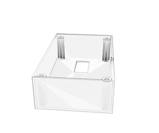
Step 3: 3D Print Your Casing

Using the .stl files provided, print both the top and bottom (labeled "Projecttop" and "Boxbase" respectively) to have a case ready to assemble.

Step 4: Ready the Arduino

Download the .ino sketch provided labeled "ProjectSketch" and upload it to your arduino
Attachments

Step 5: Time to Wire


- Starting with the touch pad, attach 3 female to female connectors to the pins of the touch pad
- Pictured here is a black wire to the ground connector, a red wire to the live connector, and a brown wire which is the wire that will be connected to pin 2 of the arduino
- Now with a male to male connector, keeping record of what each wire is for, pin the new male wire to each corresponding female connector on one side while the other side goes into a ground connection directly on the arduino, a pin labeled 5V, and the number 2 pin
- Next we move on to the L298 motor driver where you first attach an IIC cable to the driver noting where pins 1 and 2 match up
- Following through the IIC cable, connect male to male jumpers on the the drivers pin 1 and 2
- The other end of this jumper will then be going into the arduino on pins 5 and 6
- Make sure the pin that touches the driver's number 1 goes into the arduino's 5 and number 2 goes into arduino's 6
- Next you take your external airsoft battery, which in this case is a 7.4V battery, and connect the live side to the motor drivers VCC pin and the neutral side to where it says GND while also sticking in a male to male connection to GND as well.
- Lastly you take the wires connected to the airsoft's motor and connect them to the motor drivers outputs 1 and 2
- The positive of the motor goes into output 1 of the drive and the neutral wire goes into output 2
Step 6: Holding It Down


Here we need to make sure that the arduino, motor driver, and touch pad are safely installed so using the holes provided on the bottom case screw in both the arduino and motor driver using 1/4" screws.
- The arduino is positioned on one of the walls while the motor driver belongs in the holes positioned on the bottom
- Feed the touchpad wires through the remaining holes on the wall of the box so that the touch pad is connected on the outside while the wires remain on the inside
- Lastly place the airsoft inside the cutout of the box where it should be a snug fit
Step 7: Sealing the Deal, Finishing Touches

Using a power adapter, connect a 9V battery to the arduino and then fit the top casing to the airsoft where you will finally be ready to put the remaining screws to keep the case on and then you are complete with a project in hand.


