

Introduction: Yard Sign With Solar Powered Flashing LED Lights


I wanted to improve the "visibility" of my yard sign by adding solar powered flashing LED lights like I've seen on traffic signs. Discovering that commercially available traffic signs with flashing LEDs are over $1000, I decided to try to make my own.
Since yard signs available from big box stores are not very durable, I wanted to make my sign more weather resistant.
So, in summary, project goals were [1] to make or weather resistant yard sign with [2] solar powered flashing LED lamps, with [3] total cost about $100.
Supplies
Tools:
Power drill and drill bits
Hot glue gun
Staple gun
Soldering station
Screwdrivers, pilers, and wrenches
Table saw
Large Permanent markers
Utility knife
Brad Nailer
Material:
20W Solar panel kit:
Solar charge controller (I believe this is better quality controller than the one included in the solar kit):
Sealed 12 Volt battery:
Amazon.com: Replacement Battery for APC BACK-UPS ES BE550R : Health & Household
Blinking 12 volt LEDs:
Amazon.com: 5mm 12v Pre-Wired Flashing Red LED - Ultra Bright (Pack of 10) : Industrial & Scientific
Hook up wire (stranded wire, 18ga), solder, heat shrink tubing, liquid electrical tape, wire couplings and female 1/4" spade connectors.
Sterilite 6 Qt Clear View Box Clear With Latches Purple : Target
3" x 3/4" corner braces, 4 pack (Menards SKU 2251815)
Small screw eye
(4X) 1" Galvanized split ring pipe hanger (Menards sku 693436)
About 4 feet of 1" PVC + pipe tee and 2X end caps
About 3 feet long, 1/8" by 1" wide Aluminum bar stock
BCX plywood about 3/4" thk. and at least 10" by 10"
BCX plywood about 1/4" thk. and at least 24" by 24"
24-in x 36-in Corrugated Plastic Blank Sign (Lowes sku 322364)
Clear Contact paper
(4x) #8 FH wood screws 3/4-inches log.
(10x) #8 Nickel Finishing Washer and #8- 32 x 3/4" lg, flat head Machine Screws and nuts
(2x) 3/8-in Straight Strut Nut (Lowes sku 3725635)
4' Steel Fence Light Duty U-Post (Menards SKU: 1712944)
(2X) 1/4-20 Carraige bolts 3" lg + nuts and washers.
(2X) 3/8-16 Carraige bolts 3" lg + nuts and washers.
(4X) 3/8-16 hex head bolts 1 1/2" lg + nuts and washers.
Loctite
mini bungee cord
Step 1: Sign Board Assembly


- Cut the mounting board from 3/4-inch thick plywood, see dwg-A and photos. (To the mounting board we'll later fasten the 1/4 thick sign backup board, a plastic electrical junction box, and a steel vertical post). The groove in the morning board is to accommodate the perimeter rib around the bottom of the plastic junction box, so as to allow the box to sit flat. I cut the groove I used a table saw, but you could also use a router. The two drilled 1/8 diameter holes as shown to allow alignment to 24 by 24 sign backup board.
- Attach the 1/4-inch thick by 24 X 24 sign backup board to the mounting board using for #8 flat head wood screws 3/4-inch long, and wood glue, see dwg-B.
- Drill two 1/8 holes through sign backup board using the 1/8-inch mounting board holes as a guide. Then on the front face of the sign backup board use a 3/4-inch Forstner bit to create a counter bore to accommodate the 1/4-inch carriage bolt heads, see photo. Finally, enlarge the 1/8-inch holes to 1/4 inch to allow the bolts to pass through both the backup sign board and the mounting board, see photo.
- Drill 5 equally spaced, 1/4-inch holes one inch from the top off the sign backup board as shown see dwg-B. These holes will mount the LED's.
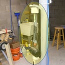
- Attach the electrical junction box to mounting board using construction adhesive (see photos). Note how the rib at the bottom of the box this provided clearance via the one-inch-wide groove cut in the mounting board.
- Create a battery holder at the bottom of the box using four, 3 inch "L" brackets. Also install screw eye to provide mini bungee cord anchor point to hold the battery. Optionally use bicycle inner tubes over the brackets for cushioning the battery. Test fit that the battery sits properly and has clearance with box lid. See photos.
- Fabricate a mounting bracket for the solar charge controller out of 3/4-inch-thick plywood. Cut one block 4 7/8-inch long by 2 3/4-inches wide, and two blocks two and 2 3/4-inches wide by 2 1/2-inches long. Attached together in a U shape with glue and brads has shown in photos. Attached the bracket near the top of the box using a wood screw as shown. Test fit for clearance, attach solar charge controller with small wood screws.
- Attach the lid to the electrical junction box and apply a protective coat of primer, and if you choose paint. Install two 3-inch long, 1/4 carriage bolts as shown in photo - IMPORTANT - Be sure to do this now because you won't be able to after completing the next step.
- Write your message on four-millimeter-thick plastic signboard 20 by 24 inches using a permanent magic marker(s). For extra protection, apply clear contact paper on top. Attach to the sign backup board using #8 machine screws, finishing washers and nuts as shown.
Step 2: Wiring


- Insert LEDs into their 1/4-inch mounting holes and solder all five LED's together in a parallel circuit as shown in DWG-C. Each solder joint was covered with liquid tape and heat shrink tubing. A 1/4-inch hole was drilled in the bottom of the electric junction box to allow the wire to connect to solar charge controller. The LEDs are held in place with hot glue, and the wiring harness restrained using a combination of staples and zip-ties as shown in photos.
- Tin with solder the wire ends which will be inserted into the screw terminals of the solar charge controller (see photo). This is IMPORTANT to ensure the integrity of the connection of ALL WIRES going into to controller screw terminals (battery, solar panel and LEDS).
- Extend solar panel leads using crimp couplings to red and black18 gauge stranded wire long enough to reach the solar charge controller inside the electric junction box.
- Attach 1/4-inch female spade style connectors to about 1 foot of red and black wire to create a lead from the battery to the solar charge controller.
Step 3: Solar Panel Mount


- Cut 2 solar panel frame cross members from 1/8 by 1-inch thick aluminum bar stock and attach to the frame using #8 machine screws nuts and washers, and secure with Loctite.
- Create a giant "T" using one inch PVC pipe, pipe tee and two end caps. The vertical section of the "T" should be extra long, about 18 inches or more. You can always cut it shorter after testing during final installation.
- Drill holes 3/8 holes in the aluminum cross members two mount pipe hangers as show. Use 3/8 hex bolts nuts and washers to attach the split ring pipe hangers and test that the giant "T swivels freely. Note - extra nuts and washers were required because off-the-self bolts of the correct length weren't available. Secure with Loctite
Step 4: Installation, Final Wiring, Initial Startup


- Drive the U post into the ground at least 1 foot deep. Try to drive a post in straight, at least straighter than I did! IMPORTANT - the open part of "U" in the U post is the post side that attaches to the backside of the sign mounting board with the two 1/4-inch carriage bolts installed previously.
- Determine which two of the 1/4-inch holes in the U post will be used to mount the sign, and to the mount solar panel. The sign requires 2 holes slightly larger than 1/4-inch diameter and six inches apart. the solar panel requires two holes about 3/8-inch diameter and 12 inches apart. See photos for help and mark the hole locations. Then enlarge the four holes as needed to mount the sign and solar panel.
- Attach pipe hanger to the highest hole using a 3/8-inch carriage bolt and other hardware has shown in the photo. The thick metal plate is actually a spring nut with the spring removed (see photos). A carriage bolt is used instead of a hex bolt, because a carriage bolted is threaded the whole length. Note that the pipe hanger is mounted on the closed side of the post "U". Secure with Loctite and install another pipe using the second 3/8 hole located 12 inches down the post.
- Slip the PVC solar panel mounting pipe through the pipe hangers you just installed. By loosening the pipe hangers, you can now adjust the solar panel rotation and tilt to take do best take advantage of the sun's rays. Then re-tighten pipe hangers. Also see Solar Panel Tilt Angle Calculator - Footprint Hero
- Attach the sign using the two, 1/4-inch carriage bolts, nuts and washers as shown. Note that the sign is mounted on the open side of the post "U".
- Fully charge and install the battery.
- Read the controller manual by opening PWM Solar Controller Renogy.pdf . At this point 3 pairs a red/black wires will get attached to the controller via the screw terminals. For easy, secure connection, ensure all wire ends are tinned as described above. You MUST connect the wires in a certain order to the solar charge controller as described on pages 7-10 of the manual.
- Re-Program the Load Terminal Mode. After completing the wiring, you'll probably be disappointed the LEDS don't illuminate. Most likely, because the Load Terminal Mode defaults to "0" which means - the load terminals won't be powered when the solar panel sees sunlight, that is the load terminals (LEDs) will only be powered on at nighttime. To fix this, reprogram to mode #17 this will power on the load terminals 24/7. See pages 14-15 of the manual for reprogramming instructions.
- That's it, just re-install the junction box locking cover.
Attachments

Step 5: End Notes
My solar sign went into service February 11, 2023, and has continued to operate without requiring adjustment or repair.
I have noticed that portions of the message written with blue permanent mark have faded much more that those written in black, red, or green marker.
Also, despite Amazon classifying the LED as "Ultra Bright," I wish they were brighter. Commerical stop signs seem to use truck clearance marker lights, which require nearly 3.8 amps each, much more than the 0.020 mA for the LED I'm current using (see attached pdf spec sheet.).
Thank you for reading my Instructable. Questions and comments invited.

Participated in the
Make it Glow Contest


