

Introduction: Your Silly Mood Swing


Good Morning
I designed and made this as a birthday gift. Then I thought we could all benefit from this, as something that we may have forgot.
While the build itself is very simple, the meaning is much deeper. The final product serves as a reminder to us all that we literally can switch our mood/anger/discomfort/grumpiness with a flip of a button, at least our mind can, if we let it.
The world can be annoying, it can get us angry, there are millions of things which we do not control, and will never will, but these all happen outside of our mind. The decision of how to relate to the world and its events is ours. It all comes down to a simple decision - do we get it get to us or do we decide what to do. And this decision can be made in a heartbeat, just as we would turn the switch on or off.
I hope you enjoy the outcome :)
Just a side note, this is not another fidget spinner!!! I really think those things got us back several decades as a species. This one is a tangible reminder of the ability that we all have, and my hope that we don't forget it.
Step 1: Get Your Parts and Print the Files


The design is simple with potential of scaling up or down. The items provided below will get you set with the current size and fit, you will need the following items:
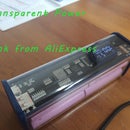
1. 1 x Lipo charging/protection board, you can get it from ebay or banggood.
2. 1 x Small Lipo cell, get it new from here or here, or use your leftovers from the small quads.
3. 1 x Switch, this one will fit the cavity perfectly, ebay or banggood.
4. 3 x Blinking LEDs, I've designed this around 2mm ones.
5. 1 x Single resistor 100-400ohm value, I used 120ohm which I had lying around.
6. Some short pieces of wire.
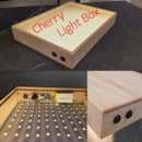
In addition, print the two attached files, which will be the base and the closure of your moodi. I'm not sure it is a free name, but this is the one I used :)
You will need a soldering iron and a hot glue gun to assemble the thing.


Step 2: Assemble the Base


The majority of electronics goes into the base, so we will start there.
First, glue in the charging board.
Next, glue the Lipo cell beside it.
Next, glue the LEDs in their holes on the perimeter.
I find it convenient to mark the positive leg of the LEDs with a sharpie in order to not mix them up once in place.
Now, do the circuit connection. The circuit is basic, we are doing the following:
1. Lipo cell is soldered to the B-/B+ of the charging board.
2. The three LEDs are soldered in parallel and go into output leads of the charging/protection board in series with the resistor and the switch.
As the base goes, solder everything with two switch wires sticking out, the switch will come later.
Step 3: Solder the Switch, Add the Closure


Once the base is assembled, solder in the switch on the two sticking wires.
Now you can check the functionality of the piece. The LEDs will blink and will go in/out of phase very quickly, which is ok.
Mount the switch into the closure.
Step 4: Glue in the Closure, Charge


Once the circuit is functional and nothing is loose, just glue the closure in.
If you need to charge it, just stick a micro usb to the bottom.
This is it.
Enjoy,
Dani


