

Introduction: Arduino Mayhew Mux Shield - Cable Connections Solutions (techshop)


Well I tested the Mayhew Mux shield and it works as advertised. I plop the shield on my arduino uno and i get 48 channels. The shield uses digital pins 2,3,4,5 and analog pins 0,1,2. So you get 48 analog inputs/outputs for the price of 7 pins.
Great, so I have 48 little wires going off to a project board - now what? a haircut - that's what. i spent sometime online trying to find a connector that was 24 wide by 3 deep.
First off - great product concept. I'll use four of them. But I don't need 5v and ground on every single pin. It didn't really complicate things that much - just that I can't find a connector that is 24 wide and 3 connectors deep.
http://mayhewlabs.com/products/arduino-mux-shield
i'm working on this project through techshop in mountain view.
Step 1: How Do Handle Wire Management With 288 Connections on a Sheild.
I've done some of this cabling before but pouring through catalogs and trying to get something to fit is a pain.
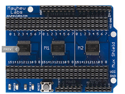
What we are faced with here are two bangs of 24 pins, each three deep. The pins on the outside of course drop down to the arduino which hosts the multiplexer shield. When I do the math it looks like 288 possible connections. These little gizmos can handle a lot of data!
There are actually only 48 signals wires, one ground, and one VCC. If you look at pin 7 on the right hand top you'll see that it has three pins. 5v, ground, and signal (which I will run to my devices).
I only need 50 connections, so there are 119 redundant positive, and 119 redundant grounds. 288 extra - sort of. But having this at the connector would be convenient for some - i'm sure. (that's a lot of wire though)
So the short answer to the above (handling 288 connections) is don't. I'm going to bring out what i need for my 48 devices and run the ground separate. I don't need VCC (+5vdc) to run to my end devices.
Step 2: Modern Device Double Height Male Headers

so - as i was fitting the cable together with standard (11mm or so) pc headers i realized that they wouldn't actually connect. they are to be soldered, and too short to fit into the female receiving end of a cable connector. (falls off).
then i remembered that modern device sells double height male headers (which I measure at about 18mm). Modern device is a great company for arduino enthusiasts. they have helped me out with some issues in the past and were generous with their time.
http://shop.moderndevice.com/products/40-pin-double-male-headers
These will fit into the connector and the arduino shield board.
Step 3: Jameco Amplatch Connectors

Also generous with time was the tech at Jameco. We spent a half hour looking through the catalog and wound up with a 50 pin connector. A 50 pin connector is two rows of 25. I'm hoping that i can use this let it hang over one pin.
http://www.jameco.com/webapp/wcs/stores/servlet/Product_10001_10001_525376_-1
But I'll only use every other pin. The first will be signal channel, the second 5 volts, third will be signal channel 2 on the mux, fourth will be 5v. I don't need 5v out on my device - rather a negative/ground and these will all be bussed together. So out of 50 wires I will use 24. It would have been great to run ground wire out too - but with this connector i can only get VCC.
I'll still split them into 24 groups and run them in pairs out to the device so i have a little more physical restraint on the cable.
Because I'm only putting 24 of the headers in there will be no VCC on any of the wires.
Step 4: Jameco Ribbon 50 Connector Rainbow Ribbon Cable

I spent another 15 minutes with the Jameco rep. They had everything in stock. Wound up with a 50 pin cable (643735). Having the colors is a life saver.
Step 5: Ribbon Connector on Mux

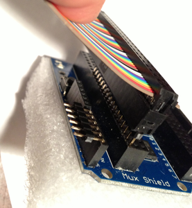
This is what it looks like on the mux. I still need to run another identical cable on the other side. Total wires 100 (50x2) . Total signals 48.
And it's easy to get twisted around when looking through cable catalogs. But the connector is two rows. So in my case (if i had put the male header into the VCC row) first wire is signal pin 0; second is vcc; third is signal pin 1; fourth is vcc - etc.
Step 6: But Wait - There's More. Getting to the Arduino Pins With Some Right Angle Headers
wiring the 48 channels complete but there is more. The arduino pins on the shield that still need wiring. (power, digital, anlog, etc).
qty 7) for mux
qty 2) for power
qty 2) for i2c connection (analog pins 3 and 4 i believe)
qty 4) leds for status
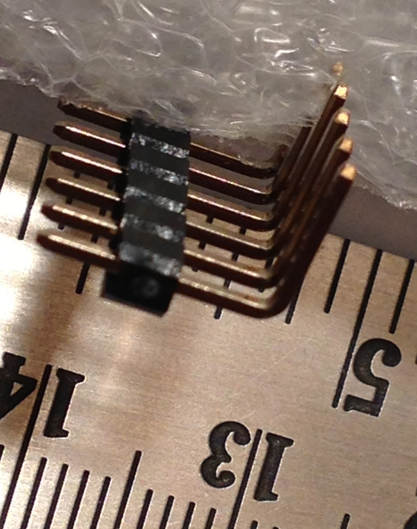
I purchased the jameco 207869, and jameco 194604 right angle male headers. i bought them in 36 pin wide - but the female connectors on the arduino don't line up directly (for example between digital 7 and digital 8; and between the analog pins and the power) so they will need to be grouped as smaller assemblies.
unfortunately these right angle headers are also too short to use with cables so they will have to be soldered. but soldering 15 headers is not much of a headache - knowing that i don't have to sweat over the 48 signal pins.
Step 7: Final Touches - Adding the Right Angle Headers to the Mayhew Mux Shield
here is the final product. i'm not using the very last two holes on the 50 pin connector as the mux has only 48 positions per bank and I'll work my way through the every other wire situation when bringing 24 wires to the end devices per side of the mux and then replicate on the other side.
i still need to solder the right angle headers which are shown on the left of picture. having saved myself the trouble of pulling 48 signals off the top by using the rainbow ribbon cable from jameco - a dozen soldered connections on the board is fine.
now - back to techshop to design some circuits for optos to drive these!
Step 8: Crimping Connectors - Vice With Soft Jaws

i don't have the tools to do this properly - so i bought lots of cable and extra connectors. but putting them in soft jaws in a shop vice worked just fine.
Step 9: Finished Connector

ok - here is the final connector. i trimmed with scissors afterwards.


