

Introduction: 10 Resistor Arduino Waveform Generator


If you have an Arduino UNO this project is practically free!
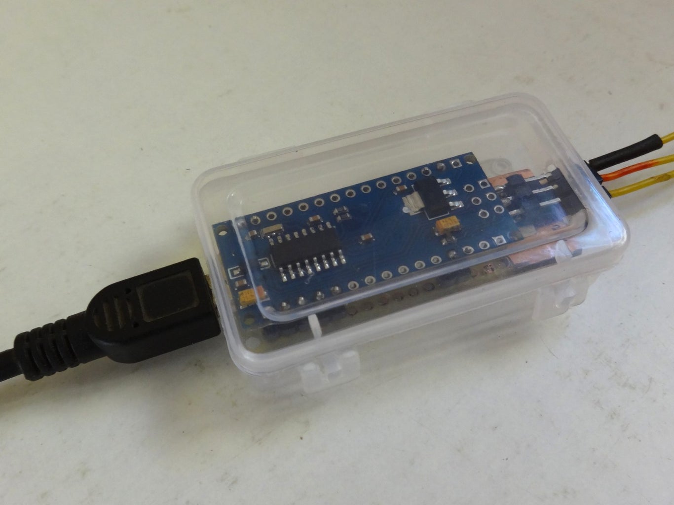
It also makes a great Arduino Nano project.
What you need (only passive components):
- Just 10 Resistors
- One filter capacitor
What you get:
- A Direct Digital Synthesis (DDS) Waveform Generator
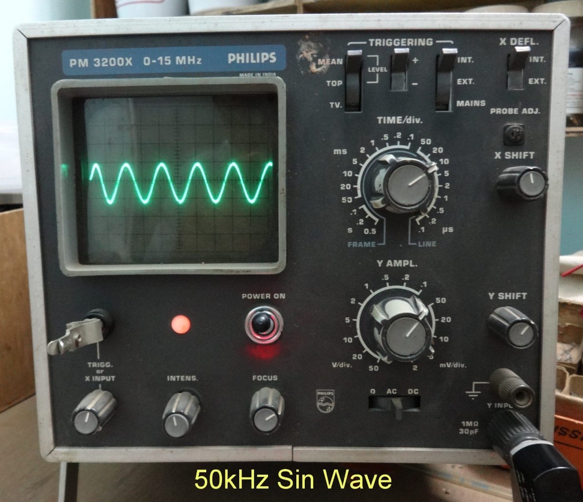
- True 50 kHz Sin-Wave capability
- Sin, Triangle, Ramp Up ,Ramp Down outputs
- And Arbitrary Waveform Generation (AWG)
Checkout:
- 50 kHz seen on an Analog Oscilloscope
- Arbitrary waveform created using a sum of f and 2f
- The arbitrary waveform spectrum
- An a compact version implemented using an Arduino Nano
Step 1: Breadboard and Circuit Schematic


The circuit implements a 6-Bit Digital to Analog Converter (DAC) using a 8-4-2-1 Resistor combination.
Arduino Uno Output pins 13 to 9 form the 6-Bits PB5 to PB0.
The Ideal resistors for the 8-4-2-1 network should have been:
1.1 K, 2.2 K, 4.4 K, 8.8 K, 17.6 K and 35. 2 K
However this has been simplified to
1.0 K, 2.2 K, 2.2 K + 2.2 K, 8.2 K + 560, 15 K + 2.7 K and 33 K + 2.2 K
The first 1.0 K instead of 1.1 K has been used to take care of the loading on the PB5 output.
A 0.01 uF filter capacitor is added to the resistor DAC output for smoothing the waveforms.
Attachments

Step 2: Something for Nerds

A basic DDS waveform generator needs a phase_accumulator to be incremented by a phase_step at a frequency f_clock.
Earlier Waveform Generators using the Arduino Uno have implemented DDS generators with a f_clock frequency based on a timer interrupt at 100 kHz. This limits the practically usable DDS waveform output frequency to f_clock /8 or waveforms to 12.5 kHz.
The current approach attempts to maximize the f_clock. By implementing the DDS loop using a while function wherein a minimum number of instructions cycles are utilized.
Exit from the while loop is based on a variable updated based on the USART Rx interrupt
The current while loop takes 43 cycles and the f_clock would be 16 MHz/43 = 372.09 kHz
The best we could have done if the Arduino Uno exit from while was based on a Reset would have been 40 instructions or 400 kHz.
f_clock/8 is 372 kHz/8 = 46.5 kHz which is practically 50 kHz!
The code is implemented in ' c' using Atmel Studio 6.0
The c-code implements a 24-Bit phase_accumulator of which the higher order 7-Bits are used as an address to a 128 step waveform table containing 6-Bit waveform data with values from 0x00 to 0x1F Hex.
Use the 007DDS.Hex to program the Arduino Uno using Avrdude.
Attachments
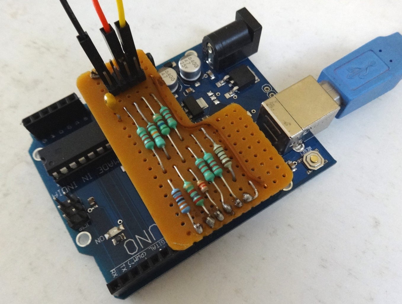
Step 3: Perf-board Circuit & Connections


The 10-Resistor circuit is wired on a standard perf-board in such a way that the PB5-PB0 terminals are on one side and two ground pins are on the opposite side. All pins match with the Arduino Uno output connectors.
Additional socket pins are soldered for the output connections.
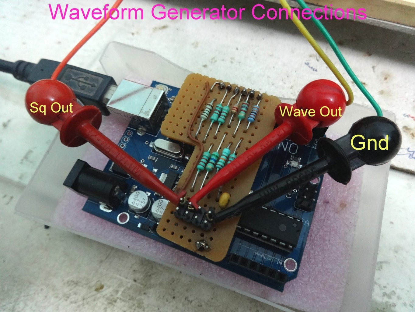
- Sq Output Reference
- DDS Waveform Out
- Gnd
The connections are shown clearly in the figure.
Step 4: Operating the Waveform Generator


Connect the perf-board 10 Resistor network to the Arduino Uno.
Connect the Arduino Uno to a PC USB port.
Open up the Windows based GUI program attached.
The GUI program is easy to use:
- It permits selection of the virtual com port
- (Try a second time if the port is not connected the first time)
- Setting the output frequency
- Selecting the waveform type
- And running the program
In the special case of the DDS_Arb (0-50kHz) arbitrary waveform selection
- The open file dialog looks for a .csv file which defines the arbitrary waveform
- Once this is selected the waveform points are automatically uploaded
- Run the arbitrary waveform at the frequency value selected.
- Once loaded the waveform points remain in memory and if the same waveform need to be re-run we can cancel .csv selection.
The third figure is a typical screen-capture showing combined GUI of the Aj_SignalGen and my earlier "USB Oscilloscope in a Matchbox " https://www.instructables.com/id/DIY-USB-OSCILLOSC... which has been used for capturing all the wave-forms in this Instructable.
To install the Windows GUI:
- Extract the Windows GUI.rar to a suitable location on the PC to be used
- Run the .exe file
- That's it!
The Windows GUI needs .Net 2.0 and has been tested on Win XP and Win 8.1
Attachments
Step 5: Amplitude Control


Output waveforms swing from 0 V to a maximum value corresponding to the 5 V supply voltage. In many applications it may be necessary to reduce the amplitude and generate waveforms which have a positive to negative swing.
This is accomplished using a external circuit where the DDS Generator output is capacitively coupled to a trimmer potentiometer and the final output taken from the potentiometer wiper point.
Considering that the 8-4-2-1 DAC has an output impedance less than 1 kilo-Ohm a potentiometer of 5 kilo-Ohm is chosen. The coupling capacitor needs to be changed depending on the frequency being used for test.
The figures show the bread-board implementation and the circuit schematic.
A 1 kHz 2V p-p waveform is shown as an example.
Step 6: Typical Sin, Triangle and Ramp Waveforms


Figures show a 25 kHz Sin, 10 kHz Triangle and two 1 kHz Ramp waveforms.
Because of the limitation of my DIY Oscilloscope the 50 kHz Sin waveform as seen on an analog oscilloscope is shown at step-1.
Step 7: Arbitrary Waveforms


Arbitrary waveform data should be created as a .csv file containing one column of data with length 128. The data values should be in decimal whole numbers in the range 0 to 63.
These values when loaded to the Arduino Uno are converted to Hex values between 0x00 and 0x1F and output as arbitrary waveforms.
Three typical waveforms with their corresponding .csv files are provided as examples.
Step 8: Implementation on the Arduino Nano
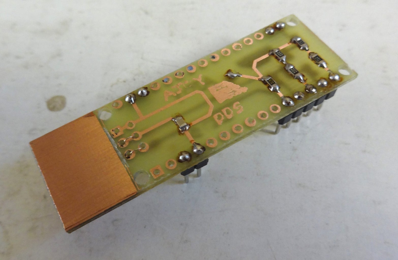


A small two layer pcb has been created using EAGLE CAD software.
The Eagle files are attached.
Unfortunately the output bits of Port_B got reversed as compared to the circuit implemented on the Arduino UNO.
This reversal in hardware is taken care by reversing the bits in software before the data is output.
This requires a changed Hex file.
008_DDS.hex to be programmed on the Arduino Nano.
The Windows GUI program remains unchanged.


