

Introduction: $10ish DIY Variable Temp Soldering Iron Controller

This instructable will show you how to make your Radioshack "firestarter" soldering iron into a variable temperature version using around $10 in parts. This idea came to me after i started lifting traces on a circuit board because I was using a 30w soldering iron to solder on a chip. Plus, I am cheap and variable temp soldering irons cost a lot more than $10. Caution: this instructable deals with household AC current. If you don't feel comfortable wiring things up or plugging things in, this is not for you. Also, this is my first instructable so I'm sorry if it sucks.
Step 1: Parts You Will Need

Tools
Flat Head Screwdriver
Wire Stripper
Tin Snips or a dremel
Hands
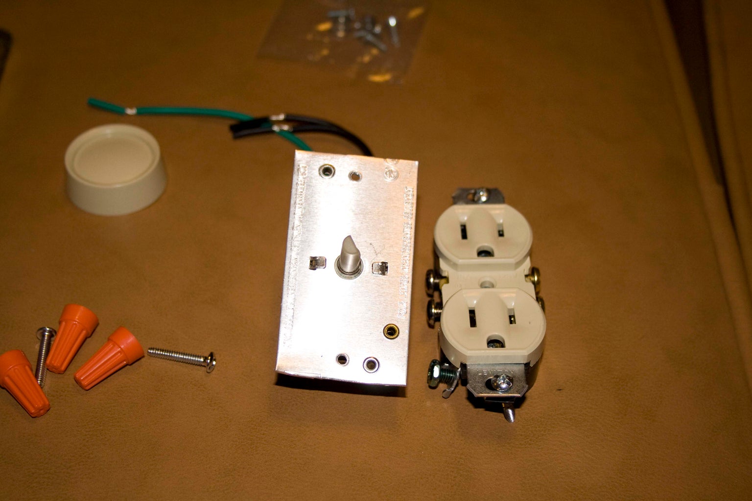
Parts
Grounded wire pigtail (mine came from a florescent light, you could just cut the end off an old computer cord. Just make sure it has clearly defined wires. (i.e hot, neutral, ground.)
Romex Connector
4" x 4" Handy Box
Outlet
4" x 4" Handy Box Outlet / Switch Cover + included screws
600w rotary light dimmer + included screws and wire nuts (mine is made by Leviton and was the most inexpensive model at home depot.)
Lamp with incandescent bulb for testing.
Step 2: Assembly

1. Take the lock nut off of the Romex connector and slide it onto the wire with the screw down clamp side towards the plug.
2. Pop out one of the holes in the handy box. I chose the top center one because it seemed like it would give me the most room to put the rest of the components in there.
3. Put the Romex connector through the hole you punched out and thread on the lock nut. Tighten it down as much as possible with your fingers. DO NOT TIGHTEN THE WIRE CLAMP YET!
4. Separate and peel apart the wires. A knife might be helpful here depending on your cord.
5. Use the wire stripper to strip about half an inch of insulation off each wire.
6. Break off the "ears" off the outlet. These are the things that stick up by the outlet screws.
7. Use a pair of tin snips (what I used) or a dremel tool to cut the excess aluminum off the lamp dimmer. Since the handy box cover has indents where the screws are, we need to modify the dimmer a bit. I cut just above the plastic screw holes on the top and bottom of the dimmer and it fit perfectly.
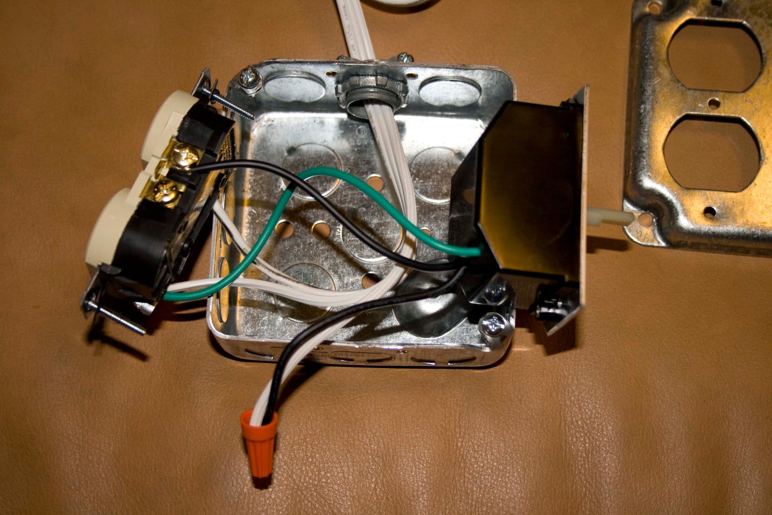
8. Wire up the components. Isolate the black (hot) wire of your pigtail (mine was conveniently marked with black insulation under the white) and attach it to one of the black wires on the dimmer with the included wire nut. Next, take the other black wire and attach it to the brass screw side of the outlet (if you look really close on the back of the outlet you'll see that it says "hot" on the brass side.) Now, isolate the white (neutral) wire of your pigtail and attach it to the silver screw side of the outlet. Finally, wrap the ground wire from the pigtail and the ground wire from the dimmer together and attach them to the ground terminal on the outlet. That's it! If you got confused your dimmer comes with a wiring diagram. Just substitute the light bulb for an outlet and you're good to go.
9. Screw the dimmer and outlet onto the handy box cover with hardware included with the cover.
10. Make sure all wires and components fit easily into the handy box and screw handy box cover to the box.
11. Make sure there there is a little bit of slack on the pigtail inside the box then tighten the screws down snug. Not so snug that you short out the wires, just snug enough to hold the pigtail securely.
12. Finally, you are ready to test! Go find a lamp with an incandescent bulb (you still have one, right?) and make sure the lamp dims when you turn the knob and goes on and off when you push. I recommend getting a marker to put a + and a - at the appropriate places on the dimmer so you don't have to guess when you plug your soldering iron into it.
13. Have a beer, you're done! (unless it didn't work, in which case you should go back and figure out what happened.)
Step 3: Conclusion
You could probably use this for a variable speed controller for a dremel tool as well, although I haven't tested it. Just make sure you don't exceed the 600w rating of your dimmer. Thinking about it now, it would be really nice to have one of those outlet / pilot light outlets so you could see if the controller is on or off. Hope you enjoyed my instructable!


