

Introduction: 12V Relay With Timer Switch


In this Instructable, we'll be learning how to use a timer switch and a 12V relay to control the extension of an Actuator. You'll be able to set the timer with up to 17 time schedules, and have the actuator extend and retract when the time is right.
No coding is required, all control comes from the timer. Any 12V power supply can be used, as long as it can deliver the current that the actuator requires (5A minimum suggested).
For this project, you will need:
- 1 x 12v Relay
- 1 x Digital Timer
- 1 x 12V battery
Step 1: Wiring the Relay


Wiring the relay creates a half bridge. When 12V is applied to Pin 8, the relay will activate. Wiring the relay as shown will cause the voltage across Pins 5 and 6 to change from -12V to +12V. The default position of the relay is when the relay is deactivated, the active position is when Pin 8 has 12V on it. The actuator can be wired in 2 ways. One way, the default position is extended, and the timer controls retraction. The other way, the default position is retracted, and the timer controls extension. For this example we're using retracted as default and extended when the relay activates. To change the actuators position when the relay is deactivated, switch the wires on Pins 5 and 6.
Wire the relay as follows:
- Connect Pin 1 to Pin 4
- Connect Pin 4 to +12V
- Connect Pin 2 to Pin 3
- Connect Pin 3 to Pin 7
- Connect Pin 7 to GND
- Connect the two wires of the actuator to Pins 5 and 6, so when the relay is deactivated, the actuator is retracted. If the relay extends, just flip the connections on 5 and 6.
See the wiring diagram for details.
Step 2: Adding the Switch


The timer is used to control when the actuator is activated. The timer is programmed to choose which times the switch is closed. This switch is connected to the relay, choosing which times the relay is active and deactivated. By wiring the switch to 12V, the timers "ON" times will correspond to the relay being activated. If you wire the switch to GND, the timers "ON" times will control when the switch is deactivated. For this example we're setting the timer's "ON" times to correspond to the relay being activated.
First things first, you need to solder wires to the timer. It doesn't matter which direction you solder the wires, polarity doesn't matter for both the switch and the power connections.
Once the timer has wires soldered to it, it can be added to the relay as follows:
- Connect one side of power to +12V
- Connect the other side of power to GND
- Connect one side of the switch to +12V (or GND)
- Connect the other side of the switch to Pin 8
Step 3: Programming the Timer
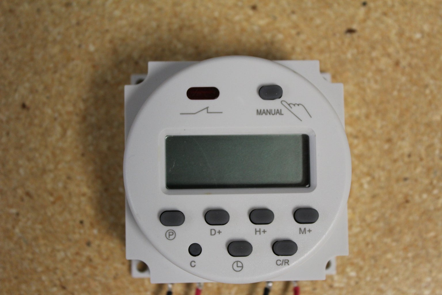

Once everything is wired up, the actuator can be tested. Pressing the "Manual" button on the timer will simulate the timer activating. The orange light will turn on and the switch will close. This should cause the relay to activate and the actuator to extend. If not, check your wiring.
The timer has the capability to hold 17 different timing programs. This gives a huge amount of flexibility, allowing you to program many different sequences to control your actuator.
First things first, you need to program the current day and time. The timer has a small internal battery so it can go without power for a short amount of time. To be safe, assume that if it loses power you'll have to reset all the settings.
Check the annotations on the image to see which button is which:
-To program the day, hold down the clock button, and press D+ until the correct day is shown.
-To program the hour, hold down the clock button, and press H+ until the correct hour is shown (its a 24 hour clock)
-To program the minute, hold down the clock button, and press M+ until the correct minutes are shown.
-To program different timing schedules, press the P button. In the bottom left, you will see a small number (1-17) with a ON or OFF below it. When you first go through the programs, they will be set to --:--. Pressing the P button again will cycle through 1 ON, 1 OFF, 2 ON, 2 OFF... and so on.
The numbers represent the program number. When you are on the ON section of the program, you are programming the times that the switch will be closed and the relay active. When you are in the OFF section of the program, you are setting the times the switch will be open and the relay deactivated.
When you are in the program menu that you want (for example, 1 ON) you can press the D+, H+, and M+ buttons to set the times. When pressing the D+ button, the days will cycle through 15 options. Each day can be chosen, weekdays only, weekends only, everyday except X day, every 2nd day... There are many options available for all your needs.
You can press the C/R (clear/reset) button when you are in the program menu to set the values to --:-- on no days or 00:00 everyday.
When you are finished programming press the clock button to return to the current time.
Step 4: Conclusion

In this Instructable, we learned to connect an actuator to a timer switch to control when the actuator extends and retracts. A project idea would be connecting an actuator to a window, to open during the day, and to lock shut at night.
If you'd like to take a look at our selection of linear actuators, motions control systems and microcontrollers then please visit us at www.progressiveautomations.com/ for all your actuator needs! We can even build a custom actuator or control system for you based on your own custom specifications with the help of our highly trained staff of engineers. You can learn more about the custom order process right here!
Follow, Like and Subscribe!
Twitter - https://twitter.com/ProgAutoInc
Facebook - https://www.facebook.com/ProgressiveAutomations
Youtube - https://www.youtube.com/user/MrActuators


