

Introduction: 16 Million Colors LED Module Arduino
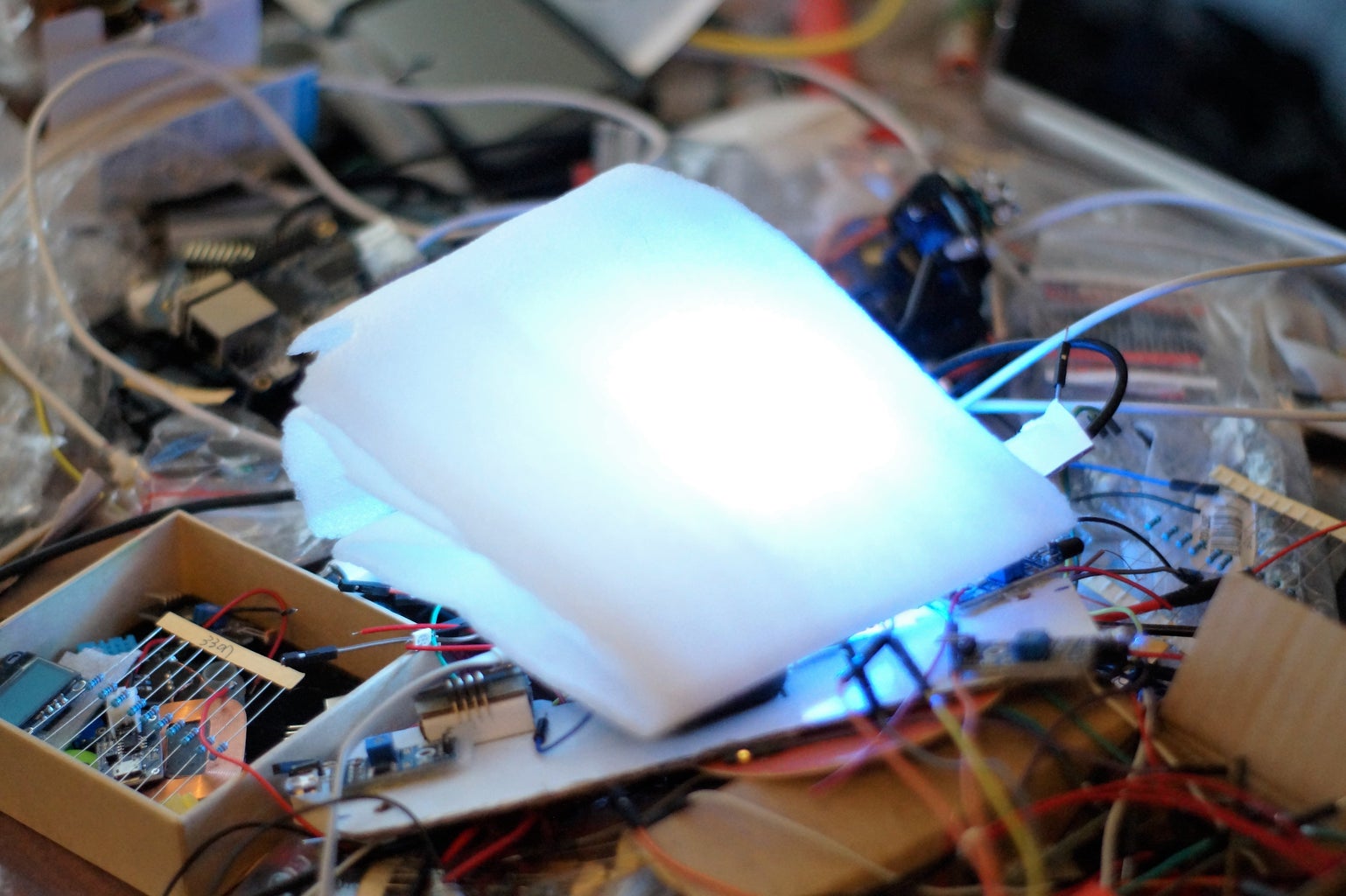


There is a solution for RGB LEDs backlight using Arduino board.
Step 1: Prepare Materials and Instruments.
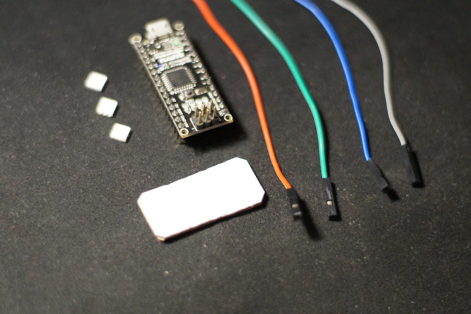


Materials and hardware:
- Arduino board or related one, with more than three PWM outputs.
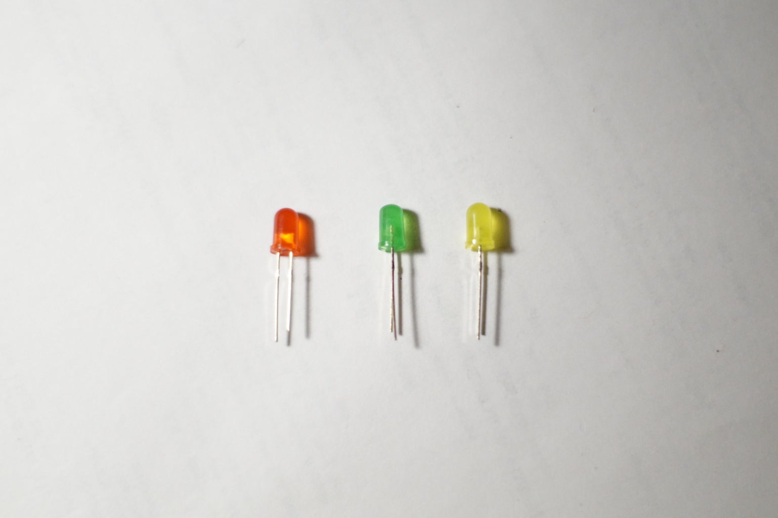
- Three Color 5 volts 40 mA LED's: Red, Green and Blue (RGB).
- Four wires to connect LED's with Arduino board.
Software:
- Arduino IDE.
Instruments:
- Soldering iron.
- Shears.
As Arduino board can be used 5 Volt version of Arduino Mega or Uno or Nano or even Pro Mini board. LED's should be able to work with Arduino PWM output, this is 5 Volts and 40 mA of current.
Step 2: Check LED's


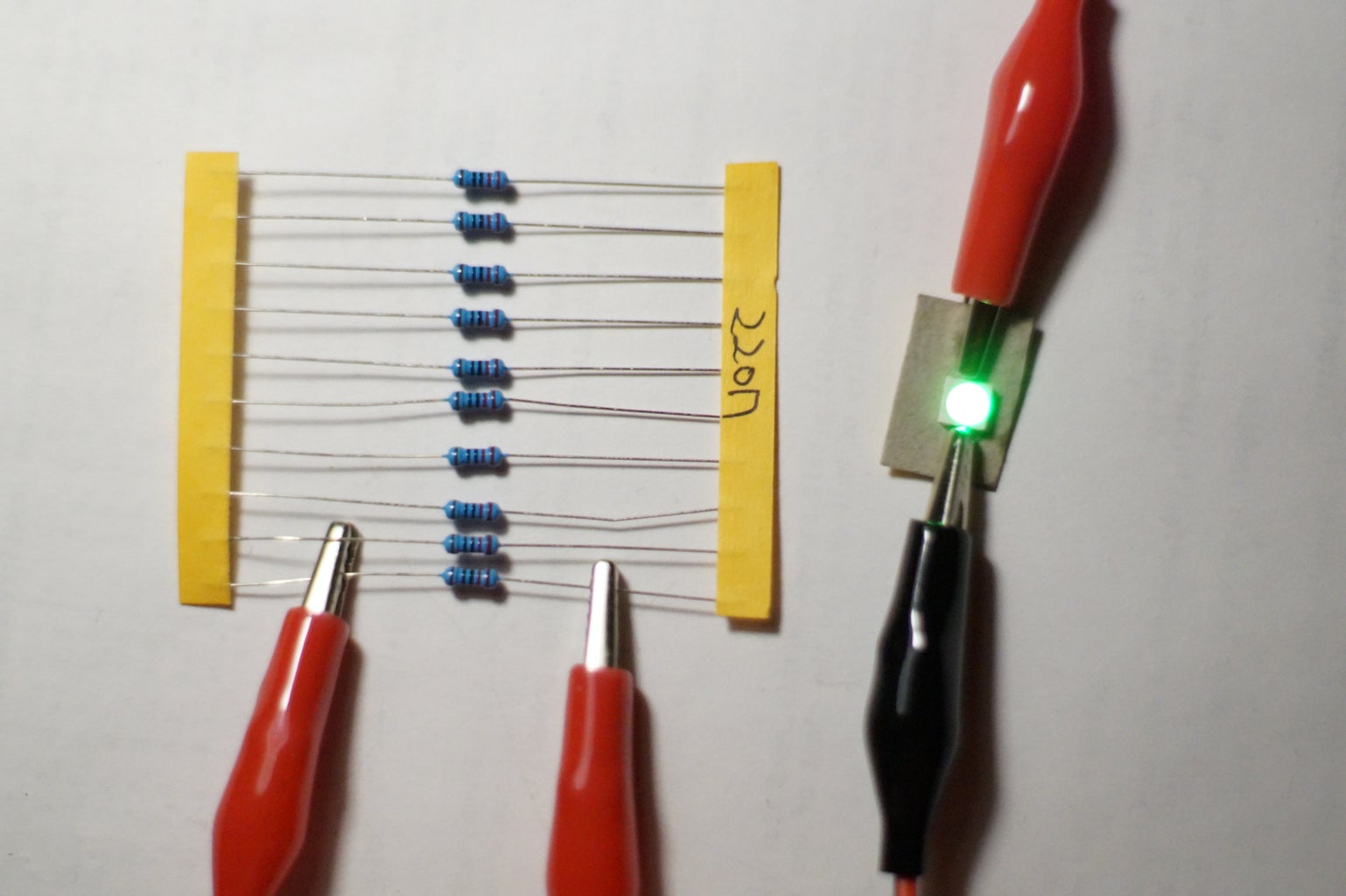
Before creating the LED module needs to check whether the LED will work fine. It's need to connect the LED to the 5 Volt power source with limited current 20 - 40 mA. This can be reached by using the 220 ohm resistor. Connect the 220 ohm resistor to tested LED, and check with 5 volts power supply: the LED should emit enough lighting.
Also, the LED can be verified directly from Arduino PWM output signal, but this will be a little bit later.
Note, that you may skip this step if you are assured that your LED will works fine.
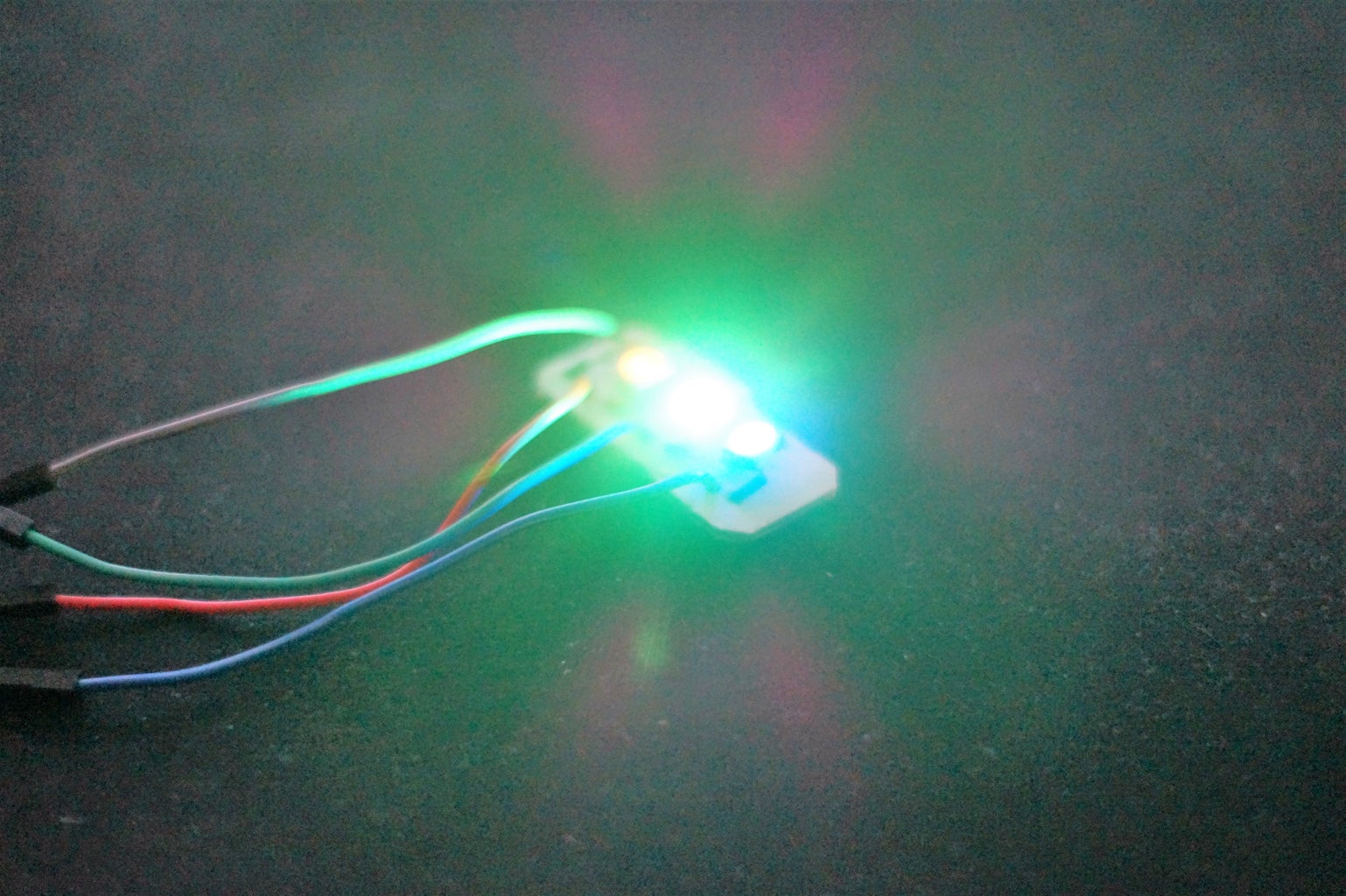
Step 3: Create the LED Module
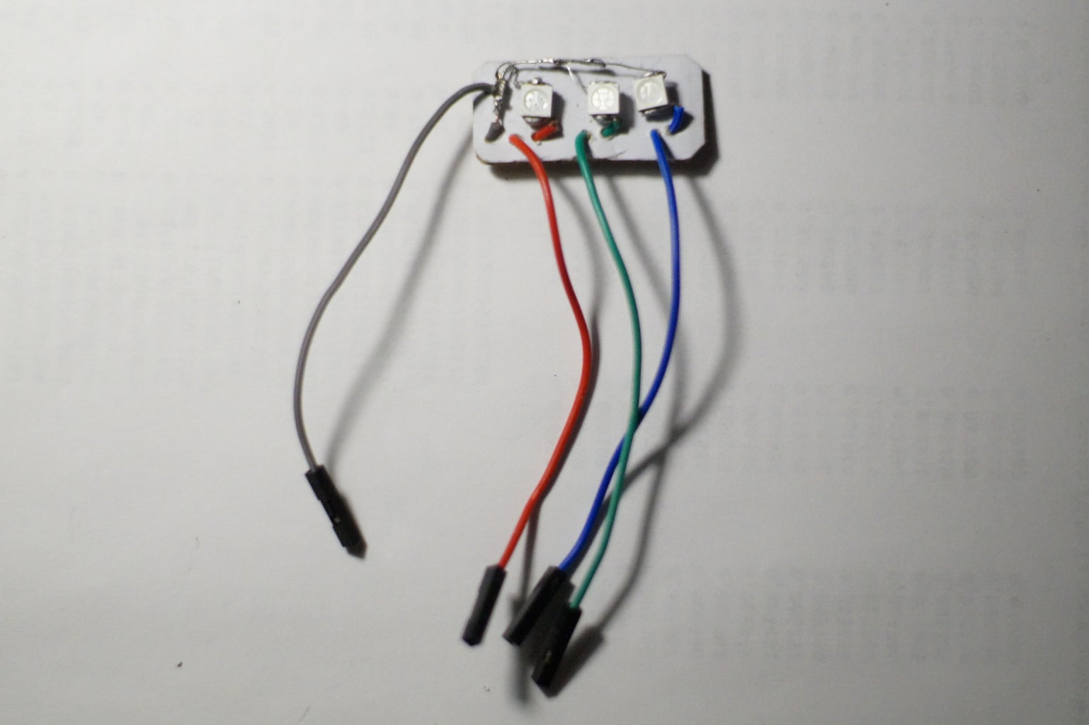
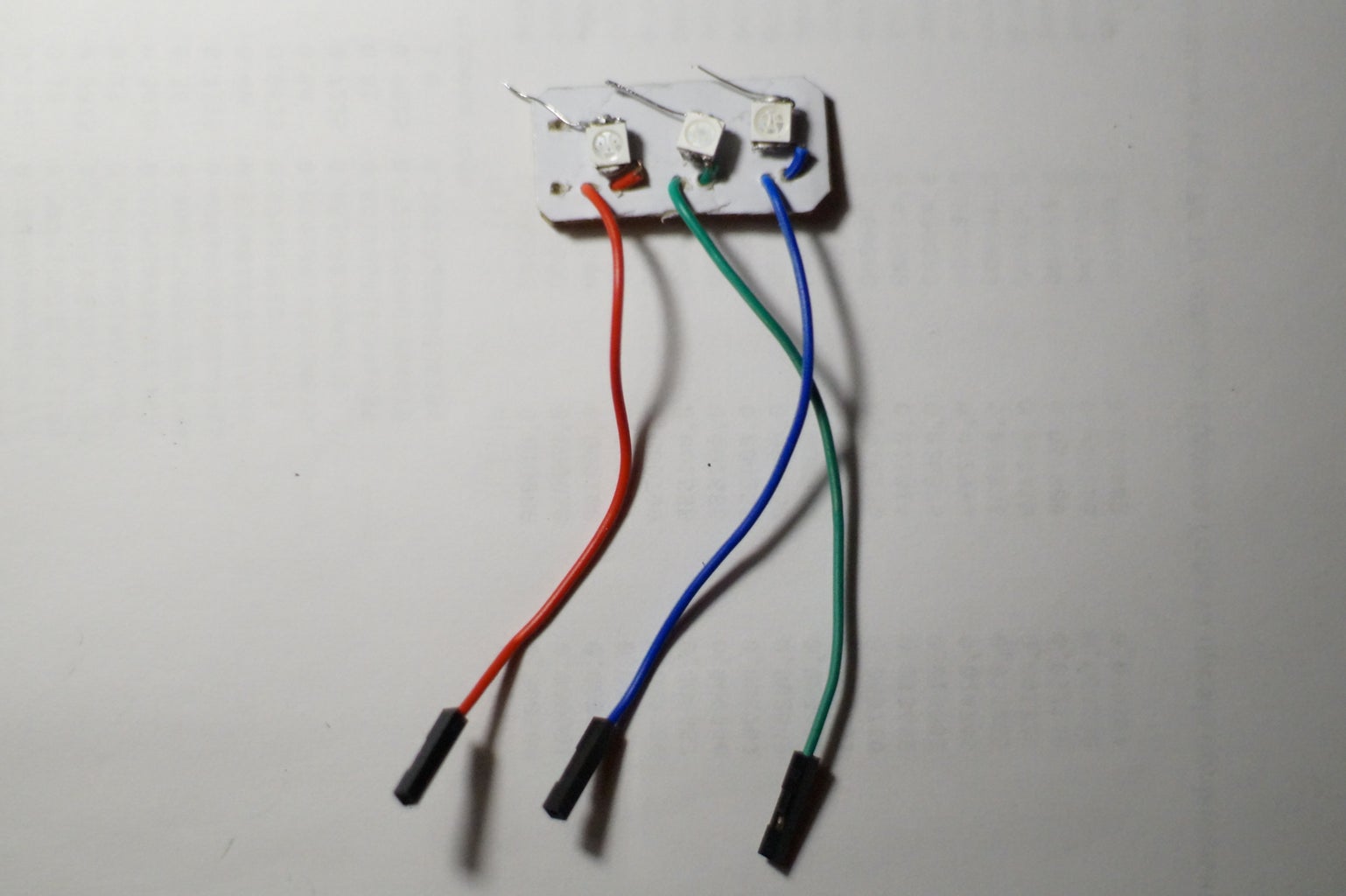

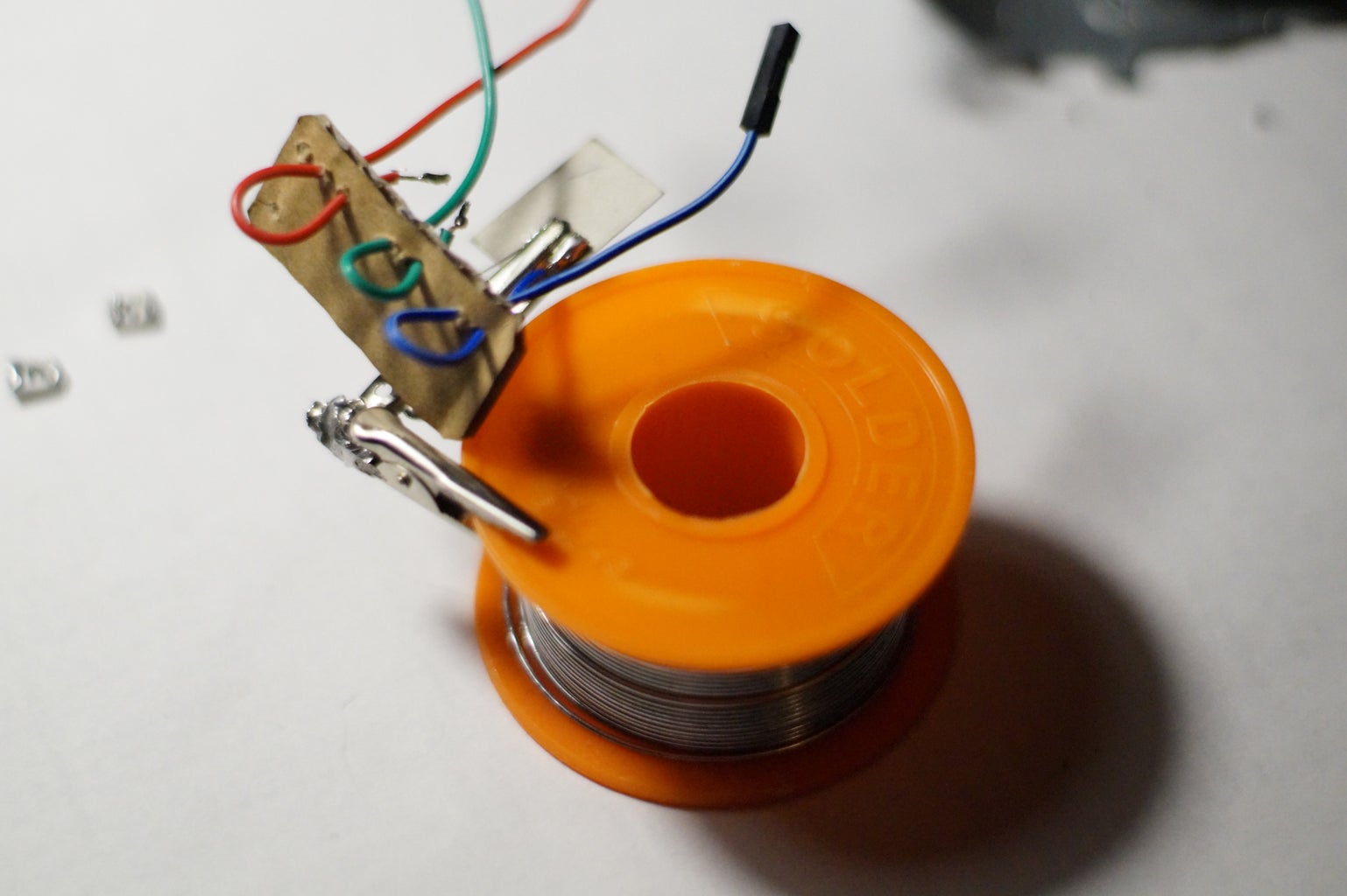

- Create the LED module base from carton.
- Solder each LED with separates "PWM" wires and one common "Ground" wire.
- Check whether wires are OK.
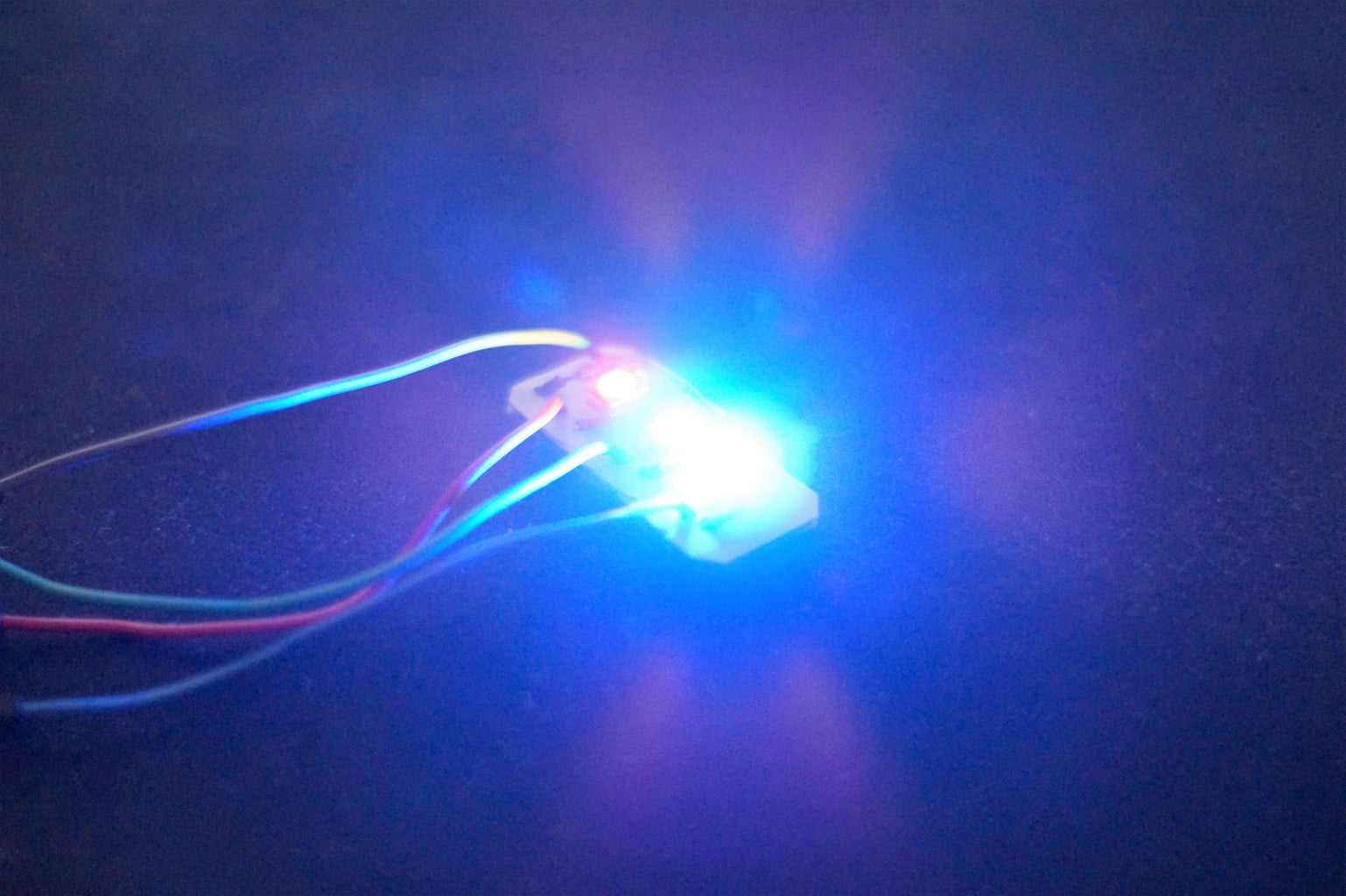
Step 4: Proof of Concept
Connect the hardware:
- Connect the "Ground" wire of LED to Ground of Arduino board.
- Connect the positive wire of LED to one of the Arduino PWM pins.
Program it:
- Open Arduino IDE, and create the new project.
- Define one of connected pins
- Send the PWM signal to mentioned pin with value in range from 0 to 255, using analogWrite(pin, value).
Arduino IDE can be downloaded by this link: https://www.arduino.cc/en/Main/Software
Step 5: Software
1. Define the basic functionality
2. Define interface.
3. Define the tests and perform the testing.
Implemented solution on GitHub:
Step 6: Further Using


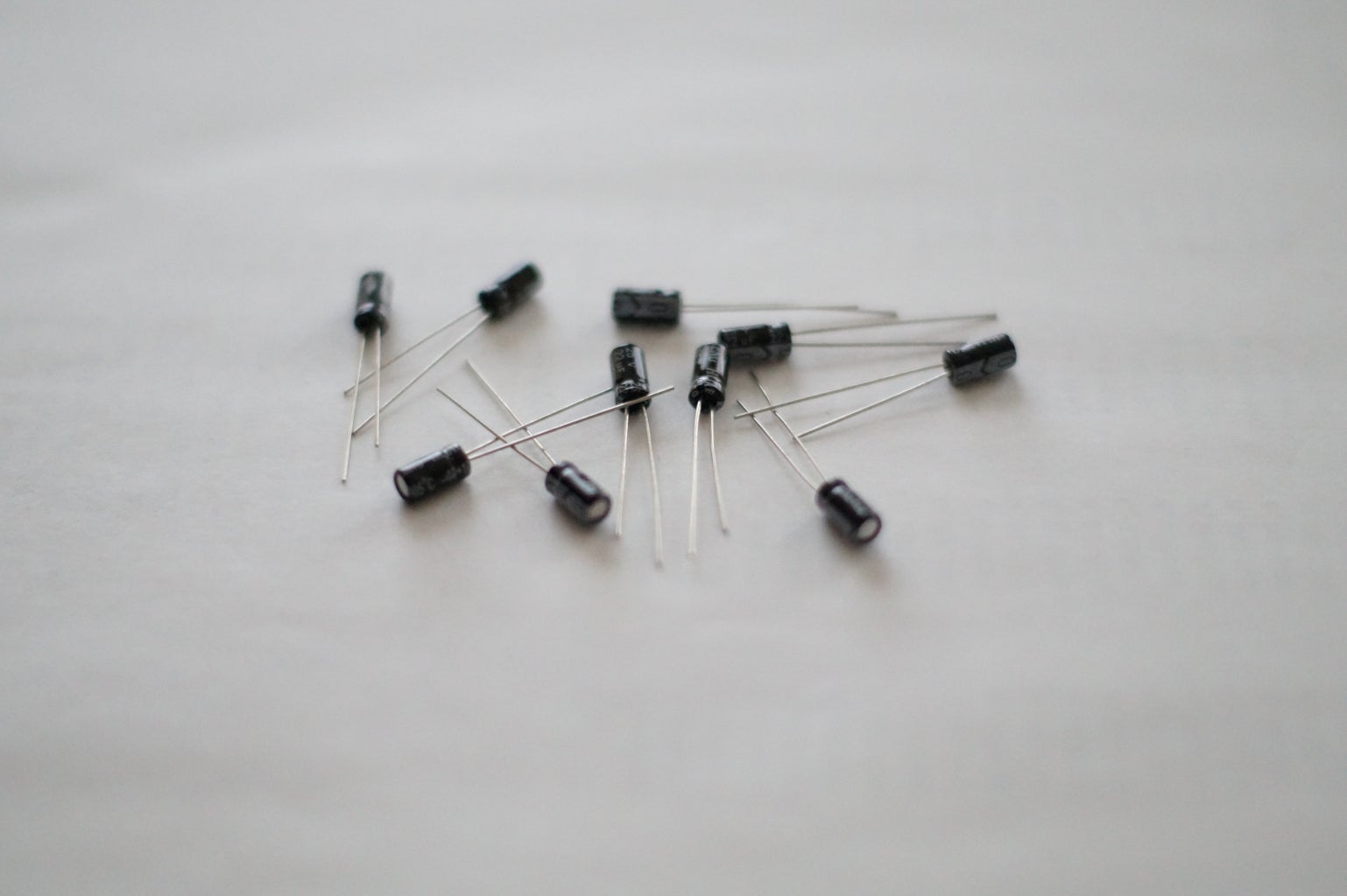
Currently this module is still a draft, and didn't tested for long time using. Additionally, it's need to protect this module from unexpected input power: it's need to add the current limiting resistors (in case of 5 Volts this will be 220 ohm resistor) for the each LED power input. To avoid LED's blinkings small capasitours on each LED can be used. Also, the caton base can be replaced by stronger one, and wires can be replaced by pinouts as in any other modules.
Regarding to software, It's need to provide the possibility to integrate this solution into another projects. Currently implemented interface is ready, Anyway, need to depply test this solution.
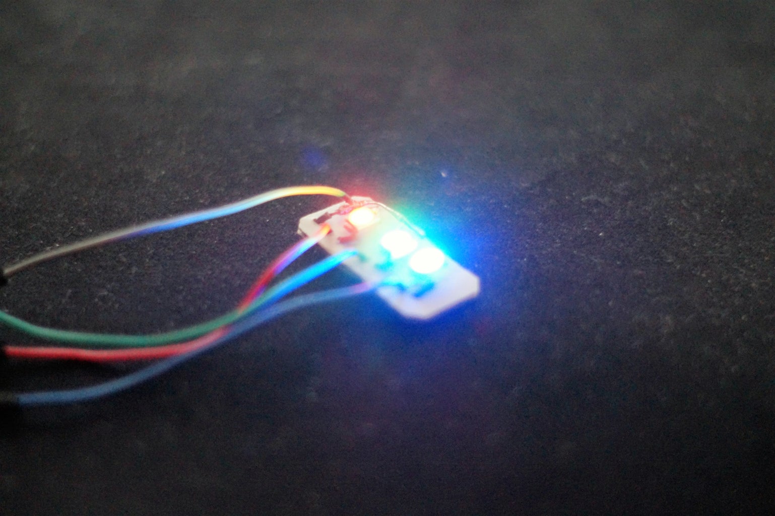
Step 7: Resume
This RGB LEDs module can be used as complete solution of any kind of indicators or backlights.

Participated in the
Microcontroller Contest 2017


