

Introduction: 2 Axis Gimbal With Arduino


Hi guys. I'm a final student in Mechanical Engineering and for Mechatronics course my group made a 2 axis gimbal with arduino from scratch.
There are some other similar projects (such as this and this) but they're either too complex, or they use commercially avaiable controllers.
We made everything from spare parts and believe the performance isn't perfect only because the motors aren't ideal.
Anyway, here's the list of material we used:
-Arduino Uno board;
-2 DC brushless motors;
-GY-80 sensor (accelerometer+gyro);
-3D printer (but you can use anything else, ofc);
-LEDs, buttons, breadboard (or ideally a PCB), and wires.
Step 1: Sensor


As mentioned we used a GY-80, but you can use any sensor that has a gyro+accelerometer.
We first tried to use only the accelerometer but soon realized it was too sensitive to movement.
The gyro alone could not be used aswell since it drifts.
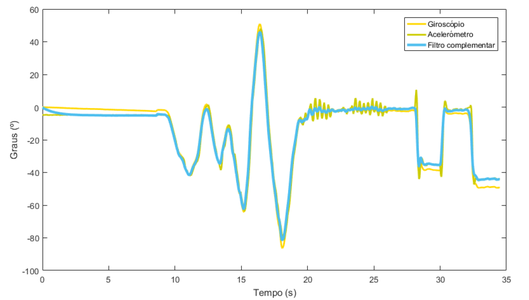
So after some investigation we found 2 ways of fusing the two:
- Using an kalman filter, which theoretically is ideal but also very computationally exigent;
- Using a simple complementary filter.
The second option worked fairly well (see graph), and we went with it.
Step 2: Actuactor

With our arduino and our sensor, we had to get some actuactors.
The only motors avaiable other than servos were small 12V DC brushless motors, (Mclennan 400-0961) equipped with a gearbox. These aren't ideal, but you work with what you got. Outer rotor DC motors would be better.
We used a H-bridge for each (specifically L293D). That allowed us to change the motor direction easily and with no concern about the motor's kickback.
Step 3: Electronics

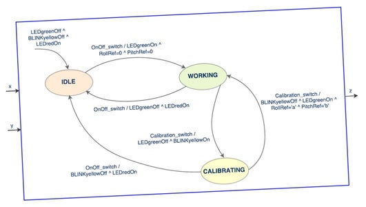
Notice the FSM (finite state machine) of the project. The user should be able to turn the gimbal ON and OFF, and also calibrate the angle of the camera, so that it doesn't necesserly stay fixed at 0º pitch and 0º roll. See the pic of the FSM.
So there are three states: working normally (a green led is on), off (red led on) and calibrating (yellow led is blinking). There are two buttons, one to turn it on/off and other to get it to calibrate.
Since making these fully portable was one of our objectives, we decided to use two sets of batteries:
- A 12V battery (in reality is a 9V battery welded to 2x3V batteries) to power the motors;
- A 9V battery to power the arduino Uno board.
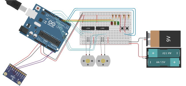
You can see the scheme of the circuit (made using this) and the picture of the real version. We used an breadboard because no PCB was avaiable.
Step 4: 3D Model


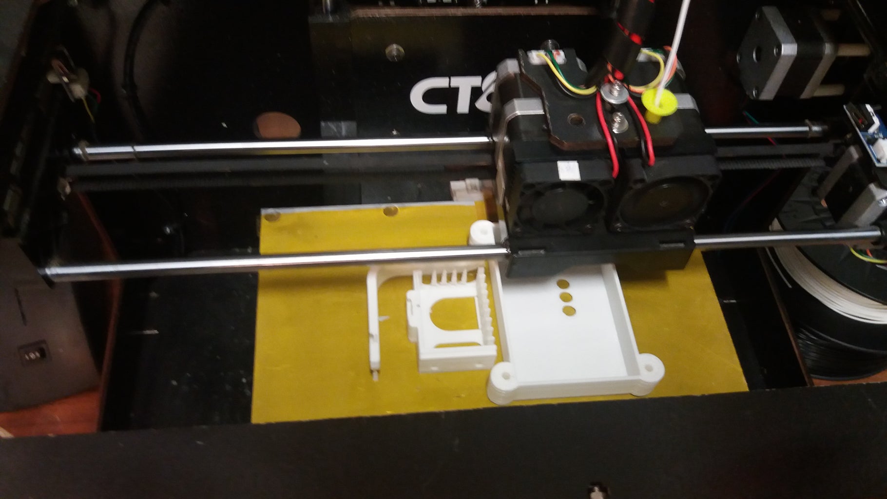
A 3D printer was available and we decided to use it. Working with SolidWorks we created, through many iterations, different parts that would latter be printed. We also bought an acrylic case for the arduino board.
We used my GoPro replica (SJCAM 4000), assembled and we were good to code.
The CAD parts are available at grabcad.
Step 5: Code

There are several libraries avaiable to communicate with the accelerometer and the gyro. We used this two: gyro and accelerometer. Both sites are in polish, but the libraries have nice examples easily understood.
Coding itself was fairly straight forward. I'll let you enjoy the challenge, but feel free to contact me if you need any help.
About the controllers, DC motors are intuitively controlled with PD, but since our motors are quite slow, we decided to use PD for the roll and PID for the pitch. This made this angle a bit oscilatory but much faster.
The graph shows the motor input vs the angle. Saturation is present but the angle error is never considerable.
Step 6: Assembly and Test
As you can see in the video above, the motors are quite slow and therefore the performance is not great.
Nevertheless, the concept was proven: no noise, fast responding system with satisfactory performance, potentially improved with the usage of more suitable motors.
I hope you enjoyed this instructable (it was my first). Feel free to ask me anything.


