

Introduction: 2-in-1 Encoder With or Without Code


This project in its first part consists of two components only: an Arduino Uno and a 4x4 Matrix Keypad. So that you can use an Arduino code with serial monitor for monitoring the keys pushed on your keypad and then you can see those symbols on your PC monitor. While without using code, you can use the same 4x4 Matrix Keypad, an IC Encoder 74C922, an IC Decoder 7447, and a Common Anode 7-segment LED display for displaying the result introduced by the key pressed on the keypad. Note that an IC74C922 requires that an hexadecimal configuration 4x4 matrix keypad be utilized (0, 1, 2, 3, 4, 5, 6, 7, 8, 9, A, B, C, D, E, F) because it also demands that the character typed on the keypad be the same that you are seeing on the display of your project. Now, I invite you to see the following video at: https://www.youtube.com/watch?v=e34_IaNiyEs
What you will need:
Soldering iron: 129040 (Jameco p/n), Solder: 94570 (Jameco p/n)
Jumper wire
Needle nose pliers
Wire strippers
Multimeter
Stickers of numbers & capital letters (size: 1cm. approx each letter and number)
Step 1: Bill of Materials


1 Arduino Uno R3 DIP Edition (Revision 3)
1 4x4 Matrix Membrane Keypad
1 Test Leads Breadboard 20 Pack 5.9 Inch (150mm) Wire Pin Contacts
1 IC74C922 Encoder for 4x4 Keypad
1 EXPERIMENTER'S PHENOLIC PROTOTYPE BOARD
1 BCD to 7 Segment Decoder Driver DIP 16, IC7447
1 Single Digit 7 Segment LED Display, CA
1 Resistor Thick Film Net 220 Ohm 2% 1.93 Watt ?100ppm ?C Isolated 16-Pin DIP Pin Through Hole Tube
1 0.1 uF 25 Volt 20% Ceramic Disc Capacitor
1 Capacitor 1 uF 50 Volt Z5u 20% Radial 5.08mm Bulk
1 Connector Unshrouded Header 40 Position 2.54mm Solder Straight Thru-Hole
1 CABLE,USB2.0,A/B,6 FEET,BLACK,USB-A MALE TO USB-B MALE
Step 2: Encoder WIth Code's Diagram

Follow carefully the project's diagram so that you can complete it successfully. Observe that this project is very easy of following because you only watch the diagram and do the connections according to your project and so you will finish it correctly without problem.
Step 3: Encoder With Code


For this part of your project, you will need an Arduino, a 4x4 Keypad, eight Arduino wires (male to male), and an USB-A to USB-B cable. The first step is to connect an end of each Arduino wire into the 4x4 Keypad.
The second step is to connect the other ends of each Arduino wires to the Arduino sockets.
That is, with the Keypad in your hands and with a free end in each Arduino wires, connect that free terminals from left to right by beginning with 2 and ending with 9 to Arduino sockets.
Once connected the Arduino wires of your Keypad from left to right by matching from pins 2 to pin 9 of the Arduino hardware, then upload the code at: http://pastebin.com/5Mmsb1JV
Step 4: Encoder Without Code


If you observe, in the photo of this step, the keypad, you can realize that it has stickers of numbers & letters. It's due to that in this project, I am utilizing an IC74C922 and therefore it requires that an hexadecimal configuration 4x4 matrix keypad be utilized (0, 1, 2, 3, 4, 5, 6, 7, 8, 9, A, B, C, D, E, F) because it also demands that the character typed on the keypad be the same that you are seeing on the display of your project.
Step 5: Encoder Without Code's Diagram

Work according to the project's diagram by following each step so that you can end this project successfully.
Step 6: Preparing the Pins


Cut eight pins of the connector header 40-position and reserve for the next step.
Step 7: Inserting the Pins


Insert the eight pins into the PCB holes by beginning from left to right and the first line above of vertical cooper lines for soldering. Then insert the smallest pins into the PCB for soldering them while yuo leave free the longest pins so that you can connect the 4x4 keypad later..
Step 8: Insert the IC74C922


Insert the 74C922 like it is seen in the photo so that you have enough space to each component that you will need to install later. Don't forget, you are going to connect the pins from left to right to 1, 2, 3, 4, 11, 10, 8, 7 of the IC74C922.
Step 9: Connecting the 74C922


For doing the connections correctly between the set of pins installed previously and the IC74C922, your best help is the project's diagram. Remembering the pins from left to right to 1, 2, 3, 4, 11, 10, 8, 7 of the 74C922.
Step 10: Installing the 7447


Once inserted the IC7447, do the connections with the rest of the components by remembering always that your best help is your schematic. From 74C922, pins 14, 15, 16, 17 to 7447, pins 6, 2, 1, 7 respectively. Also remember, you have to connect the capacitors to ground and to the IC74C922, the of 0.1uF to pin 5 and the of 1uF to pin 6 of this IC.
Step 11: Installing the Resistors of 220 Ohm


You will realize that the integrated circuit of resistors of 220 Ohm forms with each pin above and each pin bottom a resistor of 220 Ohm. Once you have defined the configuration of resistors in the IC, you can do the connections with the rest of the components.
Connect the above part of this IC of resistors of 220 Ohm to the IC7447 because it represents an end of each resistor in the IC. For example, you can connect each end from left to right to 7447 in its pins 13, 12, 11, 10, 9, 15, 14 respectively.
Step 12: Installing the LED Display


Install and solder the LED display on the PCB so that you can do the connections to the rest of components. Now, beginning from left to right, connect the bottom part of the IC Resistors of 220 ohm to common anode LED display 7-segment in its pins 7, 6, 4, 2, 1, 9, 10 respectively.
Step 13: Connecting the Positive & Negative Terminals


Draw the positive (red) and negative (green) terminals of your project so that you can supply power to it. Then the red wire represents the input positive while the green wire is the input negative to being connected the power supply of 5VDC to your project.
Step 14: Inserting the 4x4 Keypad


Insert the 4x4 matrix keypad into the set of pins previously installed so that you can see completed the project and can also use it once you are supplying power to it. Then, don't forget to set the 4x4 matrix keypad by matching exactly with the pins assembled previously for that purpose while remembering that this keypad should be connected from left to right and seen at front to IC74C922 pins 1, 2, 3, 4, 11, 10, 8, 7.
Step 15: Observe the Look of Your Keypad After Putting the Stickers on It


Observe the look of your keypad after putting the stickers on It. This is because you are using an IC74C922 that requires that an hexadecimal configuration 4x4 matrix keypad be utilized (0, 1, 2, 3, 4, 5, 6, 7, 8, 9, A, B, C, D, E, F), and it also demands that the character typed on the keypad be the same that you are seeing on the LED display 7-segment. At least the numbers from 0 to 9 because you will realize that the IC7447 decoder is not capable of generating the letters from A to F but other different characters in representation of these. For those characters, click on Data current in the following web page: http://www.jameco.com/webapp/wcs/stores/servlet /Product_10001_10001_1376122_-1
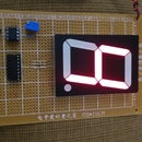
Step 16: Power the Project and Enjoy It


Once powering the project, you will difference the output answer in the LED Display 7--segment when you type a letter key on the keyboard. And the response is that you are utilizing an IC7447 decoder that generates the characters from 0 to 9 but the letters from A to F because this decoder isn't capable of generating these characters (from A to F) but others in representation of these. For those characters, click on Data current in the following web page: http://www.jameco.com/webapp/wcs/stores/servlet/Product_10001_10001_1376122_-1


