

Introduction: $20 Portable Raspberry Pi Game Console


There are tons of Raspberry Pi retro game emulators around on the internet, but most are quite expensive. With the new $5 Raspberry Pi Zero, in this Instructable I am going to show you how to build a completely portable battery powered Retro Game Emulator for $20.
In order to build the console in under $20, we will be using cheap Chinese parts and custom circuitry. If you are completely new to electronics and Raspberry Pi, you may have a hard time with this project and spend over $20 on replacement parts. Some surface mount soldering is also required, but if you are not comfortable with SMT components you can buy a pre-built board and make the console for $25.
Here is how the console is going to work:
A Raspberry Pi Zero running RetroPie will drive a cheap 2.4in ILI9341 SPI TFT. 9 SPST push buttons are used for input: four for the D-Pad, four for functions, and one button is used as a power off button. The whole unit is powered with a single cell lithium ion battery, either a 14500 cell or a old cell phone battery. a Cheap boost converter ups the battery voltage to 5V so it can be used by the Pi, and a MCP83731 battery charging circuit is used to do just that, charge the battery. Everything is safely enclosed in a two part 3D printed case.
Step 1: Gather Materials

Lets go over the parts you are going to need to purchase to build your console.
Raspberry Pi Zero $5
The cheapest, smallest Raspberry Pi yet, perfect for this project. Pick one up on Adafruit, Element 14 or Ebay.
2.4in 240x320 ILI9341SPI TFT Display $5.88
Cheap and easily interfaced with the Raspberry Pi. Good Quality and performance. Buy Here.
Lithium Ion Battery 14500 cell $0.99
These are practically the cheapest rechargeable batteries available. They claim to have a capacity of 1200mah, but that is bogus. My tests show around 400mah. One of these will give you about an hour of playing time. If you have an extra $10 go for one of these. Battery life will increase by a factor of 4. Or, if you have a old cell phone with a 3.7V lion battery in it, use that, and make your console $19. Or, if you are willing to make the console larger, wire a multitude of these batteries in parallel.
Prototyping Board $1
You will need about 7x9cm of perfboard, I got mine on ebay for $1.
Charging Circuit $3
To charge your dirt cheap batteries you will need a charging circuit. Check out my list on Mouser. You will also need a SOT-23 breakout board for the charger IC. If you do not have the skills required to build a board from a schematic or solder a SOT-23 component, you can get a pre-built charger from adafruit.
Micro USB Breakout $1.50
This will be used for charging your console. If you order the Adafruit board this part is not necessary. Buy here.
3V to 5V DC-DC Step Up Boost Converter $1.50
This is used to boost the battery voltage to a voltage usable by the Raspberry Pi. Buy Here.
Total Cost: $19.86
You will also need some wire, basic soldering tools, and the required adapters and dongles required to setup the Pi Zero. Most people already have this stuff so no extra cost.
Step 2: Install RetroPie

Lets begin this project by installing the emulation software onto the Raspberry Pi. We will be using RetroPi.
1. Start by flashing RetroPie to your SD card. You can down load the image that works with the Pi Zero here.
2. Plug in the SD card, and temporarily connect a HDMI screen and USB keyboard to the Pi Zero. If you have a USB hub use it and also connect a WiFi adapter.
3. Plug in a micro USB power supply and let the Pi boot up. It should display linux terminal messages, display the Retro Pie splash screen, reboot, display the splash screen again and then open up emulation station.
4. Press F4 to skip the gamepad setup.
5. We can now change the default settings with:
sudo raspi-config
6. Go down to advanced options and:
- disable overscan
- enable device tree
- Enable SPI plus load kernel module by default
- Also enable SSH.
7. Reboot the Pi.
8. After the Pi reboots, temporarily assign the first few controls:
- D pad to arrow keys
- A to left control
- B to left Alt
- Start to 1
- Select to 5
9. Once your in the main emulator select screen, go to "Retro Pie" and setup WiFi. If you have a WiFi adapter connected, you should now have access to the internet. If you don't, just continue on.
10. Shutdown the Pi and remove the keyboard and HDMI display. Instead, connect a WiFi Dongle. Turn on the Zero and connect to it via SSH.
If you don't have a USB hub or Micro HDMI to HDMI adapter, you can configure the Retro Pi image on a Raspberry Pi 1 or B+, and then move it to the Raspberry Pi Zero once the controls are mapped and the Pi is connected to the internet.
Step 3: Setup the TFT Display: Hardware


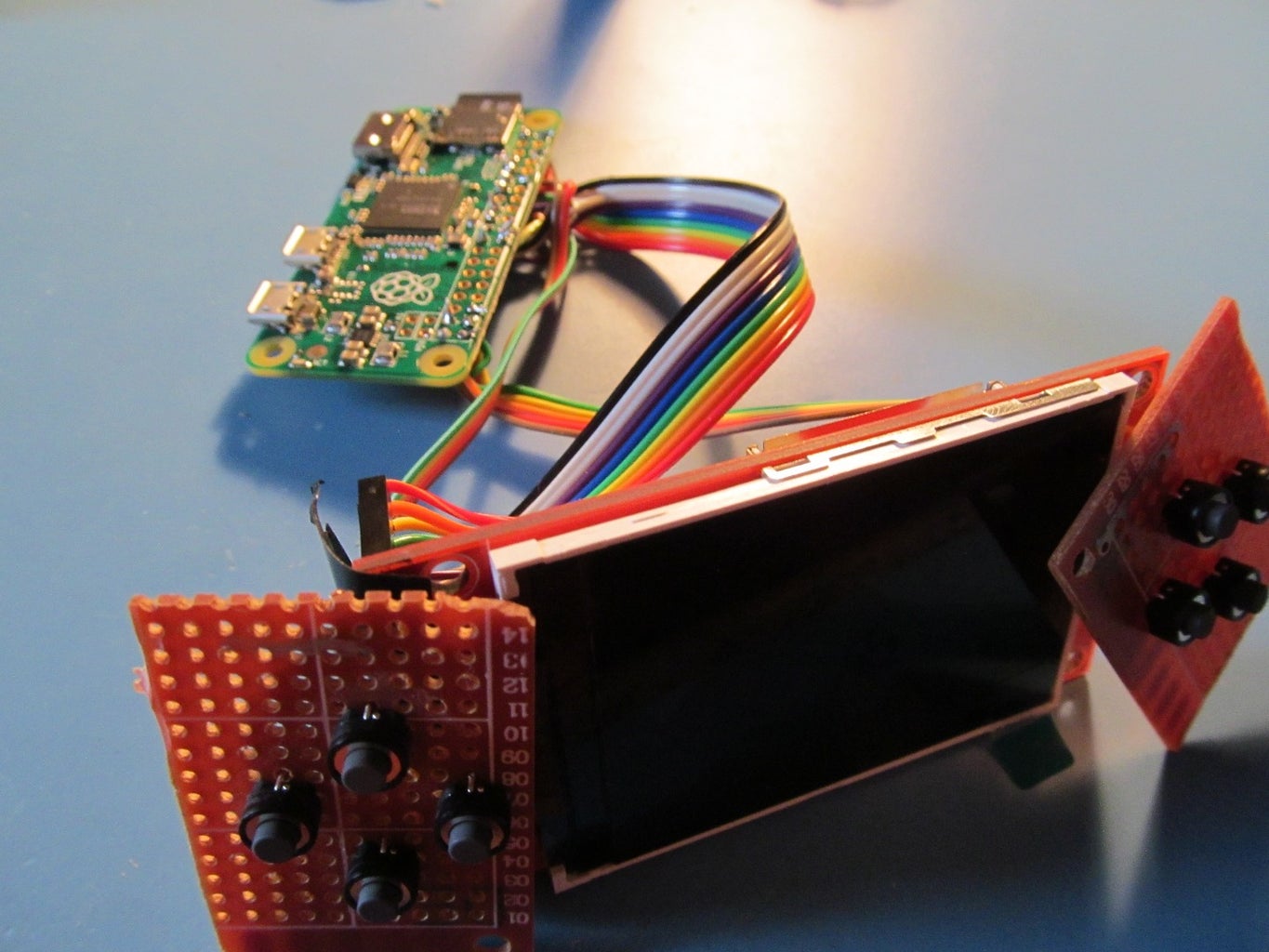
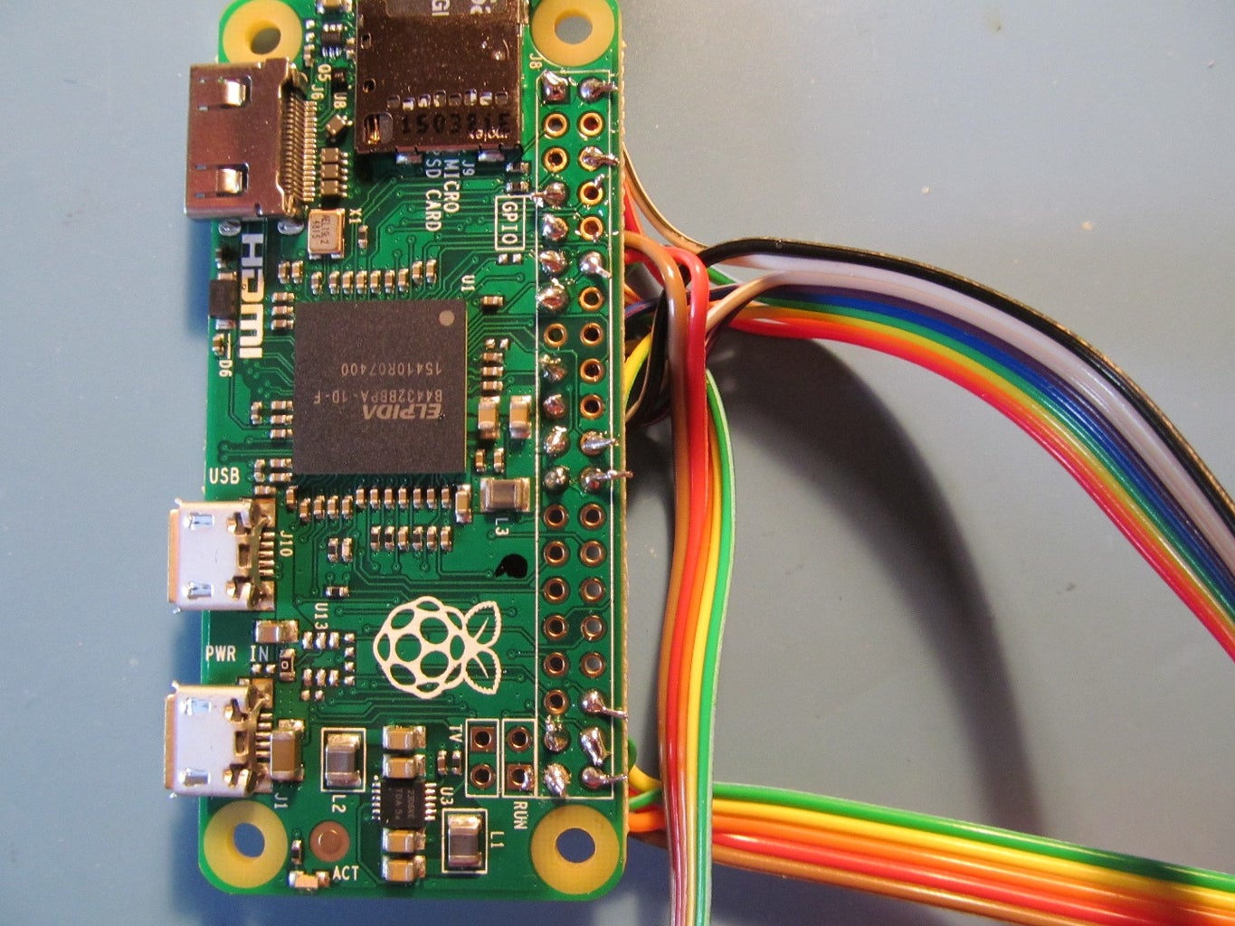
Now lets add a display. We will be using one side of female jumper wire to connect the the screen, and bare wire soldered onto the Pi Zero. Use the images above as a reference.
1. Connect VCC on the TFT to pin 2 (5V) on the Pi.
2. Connect GND on the TFT to pin 6 (GND) on the Pi.
3. Connect CS (chip select) on the TFT to pin 24 (GPIO8) on the Pi.
4. Connect RESET on the TFT to pin 17 (3.3v) on the Pi.
5. Connect DC on the TFT to pin 22 (GPIO25) on the Pi.
6. Connect SDI (MOSI) on the TFT to pin 19 (GPIO10) on the Pi.
7. Connect SCK on the TFT to pin 23 (GPIO11) on the Pi.
8. Connect LED on the TFT to pin 1 (3.3v) on the Pi.
9. Connect SDO (MISO) on the TFT to pin 21 (GPIO9) on the Pi.
Step 4: Setup the TFT Display: Software

Now that the TFT is connected to the Zero, we can install the TFT kernel and test it out.
This step of the Instructable is based on this Adafruit Guide. Thanks Phillip Burgess!
Note: Some users have been experiencing errors installing the PiTFT software. If the commands below do not work please try working through this step in the Adafruit tutorial.
1. Run the command:
curl -SLsk https://apt.adafruit.com/add-pin | sudo bash
2. Update:
sudo apt-get update
3. Install new bootloader:
sudo apt-get install raspberrypi-bootloader
4. Install TFT scripts:
sudo apt-get install adafruit-pitft-helper
5. Run helper script:
sudo adafruit-pitft-helper -t 28r
6. When you are asked if you want a console on the PiTFT, select no. Select yes for using GPIO 23 as a power button.
7. Now we can install fbcp for the display. Start by downloading it:
git clone https://github.com/tasanakorn/rpi-fbcp
8. Go into the directory and then create a build directory:
cd rpi-fbcp/
mkdir build
cd build/
9. run cmake and make:
cmake ..
make
10. And finally install it:
sudo install fbcp /usr/local/bin/fbcp
11. Now lets make fbcp start upon boot.Open up the file:
sudo nano /etc/rc.local
and add the line below right before "exit 0"
/usr/local/bin/fbcp &
12. Finally open up /boot/config.txt with:
sudo nano /boot/config.txt
Uncomment these three lines:
hdmi_force_hotplug=1
hdmi_group=2
hdmi_mode=87
Edit the pitft line to this (just changing the speend and fps)
dtoverlay=pitft28r,rotate=90,speed=80000000,fps=60
and add this line:
hdmi_cvt=320 240 60 1 0 0 0
Step 5: Setup the Buttons: D-Pad, A, B, X and Y


Once the screen is up and running, we can continue on to the buttons. This portable console uses 10.
1. Start by placing four buttons in the D-Pad formation on the perfboard as shown in the images above.
2. Bend one terminal of each button to each other to create a ground rail. Solder them all together.
3. Anchor the remaining 4 pins with solder.
4. Take a 5 wire ribbon cable and solder one wire to each anchored pin plus one to the ground rail.
5. Using a Dremel tool or a small saw, cut around the buttons. Leave clearance for mounting holes.
6. Solder the Ground wire to Ground on the Pi Zero (pin 9 using the board layout)
7. Solder the UP key to pin 11 on the Zero (GPIO17)
8. Solder the DOWN button to pin 12 on the Zero (GPIO18)
9. Solder the LEFT button to pin 13 on the Zero (GPIO27)
10. Solder the RIGHT button to pin 7 on the Zero (GPIO4)
With the D-Pad complete, we can begin work on the function buttons. they are in the exact same layout as the D-Pad, but instead of a D-Pad part over it, we have four individual buttons.
11. Start by doing steps 1-6 above to make a second button board.
12. Solder the A button to pin 40 (GPIO21)
13. Solder the B button to pin 38 (GPIO20)
14. Solder the Start button to pin 37 (GPIO26)
15. Solder the Select button to pin 36 (GPIO16)
Now that the buttons are connected, boot up the Pi and open an SSH terminal.
1. Start by downloading my modified version of Adafruit's Retrogame software:
sudo git clone https://github.com/spadgenske/Adafruit-Retrogame
2. Next, open the startup file:
sudo nano /etc/rc.local
3. Before the exit 0 line and the line you inserted in the previous step, add the line:
/home/pi/Adafruit-Retrogame/retrogame &
Save the file and reboot, and now your buttons should act just like your keyboard!
Step 6: Setup Power Button and Low Battery LED

Now we can add a power button and a LED to warn us when the battery is getting low. This is pretty simple:
1. Connect a leg of the button to ground.
2. Connect the other leg of the button to pin 16 (GPIO23)
3. Connect the positive leg of an LED to pin 15 (GPIO22)
4. Ground the other leg of the LED through a 470ohm resistor.
5.Solder in a SPDT switch for power. We will make connections to it later.
Step 7: Build the Battery Charging Circuit


This is the hardest step in the build. If you are not comfortable with reading a schematic or surface mount soldering, you can purchase a PCB with it all done for you on my Tindie store, but it will increase the cost by $5.
1. Purchase the necessary components. You will need:
- 1x 470ohm resistor
- 1x 2k resistor or 2 1k resistors
- 2x 4.7uF Capacitors or 1 10uF cap
- 1x LED
- 1x MCP73831/2 Battery Charge Controller (SOT Package)
- 1x SOT-23 Breakout board
- some .1" headers
If you order from Mouser, here are the part numbers.
Follow the schematic in the image above to build your charger. To test it out, connect a 3.7v lipo to the battery in, and 5v to VCC. The LED should come on, charging your battery. When the LED goes out, the battery is fully charged.
This schematic and the board mentioned above are Open Hardware. You can get the KiCad files here:
Step 8: Building the Power Circuit

Now we can finish up the electronics by building the power circuit.
1. Connect the negative terminal on your battery to GND ("-") on your charging circuit and the - IN terminal on the boost converter.
2. Connect the positive terminal on your battery to VBAT ("+") on the charging circuit. Also connect it to one terminal on the power slide switch.
3. Connect the other terminal of the slide switch to + IN on the boost converter.
4. Connect VCC on the micro usb breakout to 5V on the charging circuit.
5. Connect GND on the charging circuit to GND on the micro USB breakout.
6. Connect + OUT on the boost converter to 5V on the Pi.
6. Connect GND on the boost converter to GND on the Pi.
Step 9: 3D Print Enclosure

The electronics will all fit in a two part 3D printed enclosure. I printed them out in ABS on my Lulzbot Mini, but they can be uploaded to 3D Hubs or Shapeways if you don't have a 3D printer, but will put you well over the $20 budget.
If you would like to modify the models, a variety of formats are on my Github:


Step 10: Putting It All Together

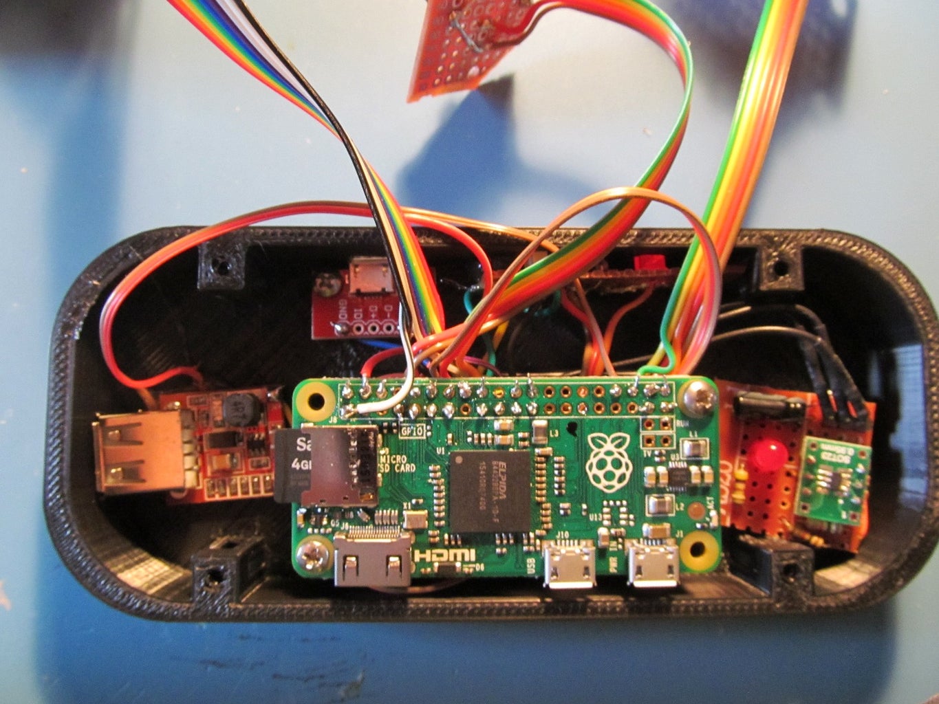


1. Lay the battery under the Pi standoffs if you are reusing a cell phone battery, or place the cylindrical cell between the Pi and the wall on the left side.
2. Hot glue the charger circuit to the right side.
3. If you are using the cylindrical cell, hot glue the boost converter under the Pi. Otherwise hot glue it on the left side.
4. Screw in the Power switch row with M2.5x 3mm machine screws.
5. Screw in the Micro USB breakout with M2.5x3mm machine screws.
6. Screw in the Raspberry Pi with M2.5x6mm machine screws.
7. Place the 3D printed button inserts in their holes.
8. Screw in the function buttons.
9. Insert the 3D printed D-Pad
10. Screw in the D-Pad buttons with M2.5x6mm screws.
11. Screw in the TFT display with M2.5x6mm machine screws.
12. Carefully screw both halves together with 4-40 machine screws.
If you are using my pre-built charger circuit instead of making one yourself, skip step 2, and instead of step 5 screw the charger circuit in the Micro USB breakouts place with M2 screws.
Your portable retro game console is complete! Feel free to contact me for help or suggestions.

Runner Up in the
3D Printing Contest 2016

Runner Up in the
Gaming Contest


