

Introduction: Flyback Transformer Driver for Beginners


The schematic has been updated with a better transistor and includes basic transistor protection in the form of a capacitor and diode. The "going further" page now includes a way to measure these illustrious voltage spikes with a voltmeter.
A flyback transformer, sometimes called a line output transformer, is used in older CRT TV's and computer monitors to produce the high voltage required to drive the CRT and electron gun. They also have auxiliary low voltage windings which the TV designers use to power other parts of the TV.
For the high voltage experimenter we use them to make high voltage arcs which is what this instructable will show you how to do. You can get flyback transformers out of old CRT monitors and TV's, they are the ones which are big and bulky. Other instructables on this website show how to remove them from the chassis and circuit board.
Disclaimer
I am in no way responsible if you mess up with this circuit.
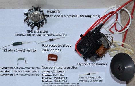
Step 1: What You'll Need


Many of these components can be pulled from old circuit boards and substitutions can often be made without issue.
1x Flyback transformer
Salvaged from an old CRT TV/monitor or purchased online (don't get ripped off, these things are worth about $15 tops when new). TV flybacks seem to perform best with this circuit, monitor flybacks don't put out as much.
1x Transistor such as MJ15003
MJ15003 works well with this driver, it can be a little bit expensive in certain places however. This is what I used for my driver.
NTE284 and 2N3773 are reported to give similar performance to MJ15003 whilst KD606 and KD503 purported to work too. The KD's are hard to get hold of cheaply these days and were more common in Eastern Europe.
2n3055 is the classic transistor often paired with this driver on the internet, but the 60v rating limits its usefulness and more often than not results in it being destroyed. The peak collector to emitter voltage easily soars above this 60v rating and clips when the transistor breaks down causing extensive heating and eventual failure of the device. So please don't use it, if you do you'll need a large capacitor like 470-1uF across it to limit the peak voltage. This will make the arcs very small too.
MJE13007 also ran poorly in my tests without further circuit modifications.
A good transistor has low turn-off delay (storage time) and fall times, decent current gain (Hfe), for example MJ15003 measures a gain of 30 with my Chinese tester.
It also needs to be rated for several amps to handle the peak currents and at-least 120v, but below 250v is preferred as the higher voltage parts such often fail to oscillate in this circuit. Many audio and linear application transistors possess these parameters.
1x Heatsink with mounting screws and nuts
(Bigger heatsink is better). The MJ15003 uses the TO-3 case style whilst the MJE13007 uses TO−220, TO-3 hardware is generally more expensive than TO−220. Those who are handy with metalwork could fabricate their own heatsink out of scrap by drilling the required mounting holes, just google TO-3 or TO−220 transistor technical drawing for more info.
A thermal pad or paste/grease is recommended for better thermal transfer between the transistor and heatsink. The cheapest and nastiest stuff you can find on ebay is adequate for this, you could even salvage enough from old LED light bulbs or the TV you took the flyback from! A pea sized amount is plenty and the transistor will squash it down and spread it out.
1x 1 watt resistor
Your power supply voltage determines the value of this resistor. 150 ohm for 6v, 220 ohm for 12v, 470 ohm for 18v. Its ok to go higher in wattage rating but not lower. I will be making a 12v driver so will reference a 220 ohm resistor from now on.
1x 22 ohm 5 watt resistor
This resistor will get hot! Allow space around it for airflow. Decreasing the resistance of this resistor will increase the power in the high voltage arc but stress the transistor more. Its ok to go higher in wattage rating but not lower.
2x Fast recovery diodes one rated for a minimum of 200v 2 amps with a reverse recovery time below 300ns, the other rated for 500mA and 50v minimum (UF4001-UF4007 works well here).
They protect the transistor from negative going voltage spikes, I just used ones found on the TV board.
For the 200v 2 amp diode I used BY229-200 but anything which meets those minimum requirements will do. MUR420 and MUR460 are the cheapest available at my local electronic store, EGP30D to EGP30K would also work along with UF5402 to UF5408.
For the other reverse diode across emitter and base I used UF4004, this one protects the base from the negative going pulse preventing transistor gain degradation.
1x Capacitor
This should be a film or foil type rated for a minimum of 150vac and between 47-560nF. This capacitor forms a quasi-resonant snubber and helps to protect the transistor from the positive going voltage turnoff spike, a larger capacitor will limit the output voltage but give extra protection, I used a 200nF (code 204) with my 12v driver. With a higher voltage transistor you can reduce the capacitance and allow the voltage to ring up to a higher level thus producing more voltage on the output.
I'll include a technique to measure the peak collector to emitter voltage with a multimeter on the "going further" page.
Wire (any old scrap will do).
For the primary and feedback coils, any wire between 18 AWG (0.75mm2) to 26 AWG (0.14mm2) will suffice, too thick and it won't fit whilst too thin and it will limit power and get hot.
Unwanted low current mains appliance power cords are a good source. I used 1 meter for the primary and 70cm for the feedback, with the 12v driver this gives plenty of extra length for experimenting with more turns, the excess can be cut off once the tuning is complete.
Enameled copper magnet wire is just too expensive per spool these days for me to recommend it, plus it has a nasty habit of scratching and shorting against the core.
Some way of connecting the components such as solder or alligator clip jumpers.
A breadboard could be used but mind the transistor and resistors don't cause it to melt!
6,12 or 18v power source at a minimum of 2 amps (more on this further on).
Step 2: Capacitor Selection


The capacitor across the transistor should look similar to those in the picture above and be rated for at-least 150 volts AC, the capacitance depends on your supply voltage, transistors collector to emitter voltage rating, number of turns on the coils (more turns = more peak collector voltage). Capacitors found in old appliances across the 120v/230v mains are good for this, they're called X class capacitors.
The aim is to have the capacitor limit the peak transistor voltage to a level which doesn't destroy it whilst still allowing it to raise high enough that there's good high voltage output from the flyback transformer. More capacitance will make the arc smaller but more flame-like. Maximum energy transfer is when the capacitor is precisely tuned to the number of turns on the coils in so called "quasi-resonant" mode.
For my 12v driver I used a 200nF film capacitor and which limited the peak voltage across the 140v rated MJ15003 to about 110v, here are some general starting values (assuming a 120v+ transistor, lower voltage transistors will need more capacitance).
- 47nF-100nF for 6v
- 150nF-220nF for 12v
- 220nF-560nF for 18v
For best results this capacitor along with the diode need to be physically close to the transistor to minimize the effects of parasitic circuit inductance.
You can measure the peak collector to emitter voltage with voltmeter using an additional capacitor and diode as shown in one of the images above.
Step 3: Wind the Two Coils


Wind two separate coils around the core. 8 turns primary and 4 turns feedback is a good starting point for 12v, a bit less of both for 6v and a few more primary turns for 18v. Experimentation is recommended and the output power can be controlled this way, less feedback turns will result in a weaker arc whilst more primary turns will give more output voltage.
I don't recommend enameled wire as the insulation layer has a habit of being scratched off by the edges of the core and shorting to it, plus its expensive these days! The core is actually conductive measuring about 10kohm end to end, so any damaged areas of enamelled wire insulation is like connecting a parasitic resistor between them.
Question: Why can't I use the built in coils?
Answer: I've done this in the past with some success, it's loud and screechy like nails on a chalkboard. Plus it can be a nuisance finding which coils to use, best bet is to google your flybacks model number and see if places like HR diemen have schematics.
Step 4: Mount the Transistor to the Heatsink


Apply a dab of thermal compound or insert the thermal pad, spread evenly, then mount the transistor onto the heat sink.
The heatsink is important as the transistor dissipates power as heat. I bought the cheapest heatsink I could find, but bigger is better. The transistor I used is of the TO-3 case style
Don't let the legs of the transistor touch the metal heatsink or else you'll be shorting the base and emitter to the collector.
I just used random screws and nuts I found in the garage, but they're pretty cheap on places like ebay or at local hardware stores.
Q: Can I use a PNP transistor?
A: Yes, but you will have to essentially build the circuit backwards for a positive ground, see the "going further" page for an PNP driver schematic.
Q: Is the heatsink really needed?
A: Yes, if you are wanting to use this circuit for more than 10 seconds the heatsink is vital as the transistor gets hot.
Q: Can I use a MOSFET?
A: No, a MOSFET will not work for this circuit (other self oscillating circuits designed for single MOSFETs are out there).
Step 5: Connecting Wire to the Transistors Collector

The metal case of the transistor is the collector, that means an electrical connection needs making to it. Ring crimps or solder lugs are the correct way to do it, but if you don't have these you can just wrap some wire around the screw. It won't be as mechanically sound as the "correct" way, but it will work.
Step 6: Putting the Circuit Together
In the graphical diagram, the red coil is the primary with one end connecting to the positive "+" of the power supply/battery, the other end connects to the transistors collector which is actually the metal casing of the transistor itself if a T0-3 such as the MJ15003 transistor is used.
The green coil is the feedback with one end connecting to the middle point of the two resistors, and the other to the base of the transistor (looking at the MJ15003 underside this is the pin on the left).
Step 7: Powering the Circuit

To power the circuit I recommend a power source which can supply a minimum of 2 amps, lower will most likely work but will limit the output.
Add more turns on both windings to increase power, (contrary to what I've read online), this lowers the operating frequency and allows more primary current to ramp up. The number of turns gives a rudimentary form of current limiting along with the top resistor (higher resistance = less base current and less arc power).
Bench power supply Self explanatory really, if the current limit is set too low the circuit may fail to oscillate.
Wall Wart/charger You can use these, but be mindful of their voltage and current ratings. The switched mode variety will most likely go into self limiting/shut down if the maximum current rating is exceeded.
Salvaged transformer Done this myself for my 12v driver, a 48VA transformer which puts out 9v AC will give roughly 12v DC 3 amps when rectified and smoothed. A 4700uF 25v capacitor will give plenty of smoothing, I'd go with 50v 4 amp bridge rectifier diodes minimum.
Lithium cells in series are great as they can supply lots of current.
Drill batteries are fine, most are 18v so use the 18v circuit.
AA batteries in series are fine, the arcs will just gradually become smaller and smaller as they become depleted. An AA cell is considered spent when it drops below 0.9v at rest, but many can still power other loads even when they're no longer able to supply the juice for this circuit.
A 12v lead acid battery is a very good way of powering this circuit.
12v car battery see above.
6v lantern batteries will power this circuit for a long time before the arcs start getting small. These are not too common nowadays and are pretty expensive, don't waste your money if cheaper options are available!
AAA batteries will work for a while but won't last as long as the larger AA cells, they also have a higher internal resistance so will waste more power as battery heat.
9v/PP3 batteries will give a few minutes play when new before the arcs become smaller and the circuit stops working. The upper resistor will probably need to be around 180 ohms for 9v, but I didn't make a 9v driver schematic as it would probably lead people to using 9v PP3 batteries and disappointment.
Step 8: Safety First!


When drawing arcs...
I strongly urge you to make a "chicken stick" which is an insulating stick where you attach one of the high voltage wires to draw arcs, it's much safer than holding the high voltage wire in your hand. PVC pipe is very good for this, wood is fine too as long as its dry.
Scary warnings.
Including the obvious risk of electric shock another thing to take note of is the arc is VERY hot and can easily burn or set to fire to anything it touches. Even the cable insulation will burn if you draw the arc onto it.
If you insist on burning pieces of paper or other objects then take that into account and have some way of putting the fire out.
- Never touch the high voltage wire or the flyback when the circuit is running.
- Make sure you can easily cut power to the circuit.
- Do not use this circuit on an unsuitable surface such as bare metal or easily flammable surface.
- The transistor heat-sink can get hot, watch out not to burn yourself.
- The 22 ohm resistor will run hot.
- The primary coil and transistor collector can ring up to a few hundred volts, don't touch these either.
- Keep high voltage cables away from other parts of the circuit.
- Keep pets away. As well as the risk of shocking your pet from the sparks many pets like to chew things such as wires, the high frequency noise may upset animals too even if you can't hear it.
Disclaimer
I am in no way responsible if you mess up or hurt yourself or others with this circuit.
Step 9: Finding the High Voltage Return Pin


To find the high voltage return first attach your chicken stick to the high voltage out (the big thick red wire), then turn the circuit on. You should hear a high pitch noise, if you don't hear this noise then go to the troubleshooting page.
Bring the chicken stick close to the pins on the bottom of the flyback and go past each one individually. Some of them may give a slight spark but one should give a solid constant HV arc, this will be your HV return pin. You should now disconnect your chicken stick from the HV out and connect it to the HV return pin instead, careful not to yank the return pin too hard as it may rip out.
Step 10: Troubleshooting

Problem?
- If there's no high voltage then try reversing the connections to one of the coils.
- If there's high voltage but the arc is small try reversing both the primary and feedback coil connections.
- Make sure all connections are secure and nothing is shorting out. Enamelled wire is notorious for bad connections, soldering doesn't always break through the enamel so you have to get medieval on it.
- Check the base and emitter legs on the transistor are not touching the heatsink.
- It works but the arcs are small and weak. Check the power supply voltage isn't sagging under load by measuring it with a DC voltmeter whilst drawing arcs.
- Circuit pulses on and off. This is caused by the power supply going into protection, if the maximum power supply rated current isn't being exceeded then an electrolytic capacitor of a few hundred uF across the supply rails may help.
- It works but the transistor gets very hot. Fiddle with the number of turns on the coils, reduce the feedback turn count first.
- The 22 ohm resistor gets hot, this is normal. It my 12v driver it dissipates 2w, but that's enough to get most little resistors too hot to touch. If you're not comfortable with components running too hot to touch then increase the thermal mass (upgrade to a higher wattage resistor).
- Broke the core? Glue it back together, dampening the mating surfaces with water first will help certain types of glues to stick.
Step 11: Going Further


You can measure the peak voltage spike across the transistor with the method shown in the picture, it is important to keep the peak collector to emitter voltage below the maximum rating of the transistor along within the safe operating area (about 80v at 3 amps for the MJ15003).
A transistor may appear to clamp the peak drain voltage for a while but this quickly leads to failure of the part.
PNP transistors can be used by flipping a few things around.
Long exposure photography can be used to obtain discharge patterns.
Try making a jacob's ladder by placing two rigid conductors like thick copper wire in a vertical V shape, the arc forms at the closest point near the bottom and rises at it heats the air.
HV capacitors are also interesting, you can make one by taping two pieces of kitchen foil on each side of an insulator such as a plastic container lid and running two wires to each sheet. Now connect one plate to the HV out and other to the HV return, the arcs will turn into a series of loud bright snaps! Just don't touch it as it really hurts.


