

Introduction: 3 Arduino Pins to 24+ Output Pins


Have you run out of output pins for your Arduino? Well this is the solution for you! In this tutorial I will show you the hardware and the code needed to control multiples of 8 number of outputs, using just 3 of your Arduino pins. The main idea of this Instructable is to create a module which can either operate separately or be hooked up to another module thereby increasing the outputs by another 8 pins.
Materials Required:
- Arduino UNO (atmega 328p).
- Prototype PCB Stripboard.
- 74HC595 8-Bit Shift Register.
- 1uF Electrolyte Capacitor 100v.
- 4.7k ohm 10-pin Resistor Network.
- 1k 1/4 Watt Resistors.
- 10 Segment Red LED Bargraph Array.
- 16-Pin DIP Socket.
- Male Pin Header Strip.
- Jumper Cable Female to Female.
- Breadboard Wire.
- 60W Soldering Iron.
- Solder Wire.
Uses of this project:
- A basic understanding of shift registers.
- Ability to increase your output pins to either control relays or any other output modules.
- Free the arduino pins to increase the number of sensors that can be used.
In this instructable I have tried a different approach, where I soldered the individual components on the strip board and also testing. I have also provided to you a breadboard diagram of how the circuit will look like, as well as the code with which u are capable of controlling a maximum of 40 shift registers in parallel. The main inspiration behind this tutorial is the Arduino ShiftOut tutorial.
Step 1: Introduction to the Shift Register


What is the Shift Register:
The Shift Registers fundamental purpose is to increase the number of Input/Output pins of the Micro-controller. The Shift Register used can either be a 74HC595 which is made for increasing the Output pins, While the 74HC164 is the Shift Register made to increase the Input pins. The most important point to note is that a number of Shift Registers can be cascaded. So that the Micro-controller can control 8 to the power of n Output/Inputs using just 3 pins. This cascading can also be called as daisy chaining of the Shift Registers.
Pins of The Shift Register:
The most important pins of the Shift Register are listed as follows:
Serial In (PIN 14):
The pin which shift the next input for the Shift Register.
RCK (PIN 12):
When this pin is pulled high, it will shift the register.
Serial Clock (PIN11):
Needs to be pulled high to set the output to the new Shift Register values, This must be pulled high directly after SRCLK has gone LOW again.
QH' (PIN 9):
The significance of this pin is that it can be connected to the Serial In (PIN14) of the next Shift Register and the daisy chain can increase.
Working of The Shift Register:
The shift register can be compared to a game of data moving along junctions. They will move to the other junction when the RCK pin of the shift register changes to HIGH and thus the data can be transmitted to any number of Shift Registers using the following principle. The shift register can maintain the values using the Serial Clock (PIN 11). Whenever the serial clock pin goes high then the RCK pin will go low and so on till the required data is transmitted.
I have included a 123D Circuit diagram describing the connections of the Shift Register to the Arduino. As well as the basic connections needed for the shift register to work. The second 123d circuit diagram provided shows the connections for the second Shift Register and so on.
Daisy Chaining Shift Registers:
The Shift Registers can be increased by connecting the QH' pin with the second Shift Registers Serial in (PIN 14). Thus the number of output is limited only to the number of Shift Registers that can be connected. The code which is provided with the option to connect upto 40+ Registers. I have also provided a real time diagram of the module and the connections to the arduino using the modules.
Step 2: Assembly and Soldering of the Modules - 1


As I mentioned earlier this Instructable features a different method of assembly, I use a step by step soldering tutorial. I hope its as useful as just providing the circuit and doing it on your own, In the future I will try to make it a etched PCB so that the soldering can be made even easier. The first picture shows the finished module.
Anyway the module produced will be a 4 x 3 cm square and more modules can be daisy chained and the inputs can be increased depending upon the requirement. So lets get started with the assembly!!!!
Step 1:
The first step is to insert the LED bar graph as shown in the diagram and solder up the connections.
Note 1:
Please note that the led bar graph position should be checked with a power supply so that it is properly inserted. 5V from the arduino will suffice but don't connect it for long or the LED will short. The diagram named Note1 shows me checking the module. Please ignore the resistors in the picture and just connect it directly.
Step 2:
After checking insert a 1k resistor as shown in the diagram. The need for this resistor is it provides the resistance for the final LED. This is followed by the 4k7 resistor matrix which is connected to the ground. Refer to the diagram for the position of the resistor. I have shown a 10k in the diagram but please ignore that.
Note 2:
This note is very important because the resistor matrix ground pin (♢) should be properly connected to the ground rail only then will the LED's turn on. This is crucial since the LED will be dim if the matrix is reversed.
Step 3:
So insert the resistor matrix with the diamond end (♢) on the ground end as shown in the diagram. Then solder the pins of the matrix. You can also double check the LED's by connecting the power supply.
Step 3: Assembly and Soldering of the Modules - 2


Note 3:
Before inserting the main IC just make a cut using either a compass or a blade. The cut can be checked using the continuity tester in the multimeter.
Step 4:
The IC goes in as shown and the DIP socket is used so that you can change the IC in-case of any failure. Finally solder up the joints.
Step 5:
The Shift Register can control 8 LED's But the module has 10 LED's so the extra two are controlled by the two male headers and they can be controlled by the Arduino. Solder up the joints.
Step 6:
The jumper needs to connected as shown in the diagram The connectors one end is connected to the LED bar graph and the other goes to the 15th pin of the 74HC595.
Step 7:
Next comes the power supply u need two headers connected as shown in the diagram and solder the joints.
Step 8:
Now insert two male headers on the following pins as shown in the figure. Then solder up the joints. They can be connected to either the Arduino or the next module.
Note 4:
Solder the pin shown in the diagram to the ground rail. This is easier than connecting a jumper wire.
Step 4: Assembly and Soldering of the Modules - 3
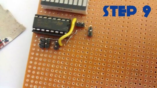


Step 9:
Connect up the breadboard wires as the jumper wires as shown and solder them on the bottom side. The jumper wires are used to send the Vcc to the IC power pins.
Step 10:
Solder the 1uF capacitor so that the negative side is soldered to the ground rail of the board and the positive rail goes to the pin as shown in the figure. Just refer the circuit diagram in the previous steps.
Step 11:
Cut the module using scissors and make the cut as compact as possible. Then your done u have your first module ready.
Just repeat the steps to create as many modules as you want and daisy chain them to increase the inputs. The output going to LED's can be sent to a relay board and can drive as many relays as you want using only the three pins of the Arduino. The last figure shows the completed modules, I have made 3 modules upto now. In the next step we test the completed module.
Step 5: Checking Your Module
Once the module is done you can check the finished module using this simple code. The code shows a led chaser and some other interesting patterns. This code is basically made for checking the module and ensure it works perfectly.
CODE:
int  data = 11;
int clock = 12;
int latch = 8;
// the animation sequence for the LED display
// first column is the LED status in binary form, second column is the timing in milliseconds
byte patterns[48] = {
  B00000001, 100,
  B00000010, 100,
  B00000100, 100,
  B00001000, 100,
  B00010000, 100,
  B00100000, 100,
  B01000000, 100,
  B10000000, 100,
  B01000000, 100,
  B00100000, 100,
  B00010000, 100,
  B00001000, 100,
  B00000100, 100,
  B00000010, 100,
  B00000001, 100,
  B00011000, 200,
  B00100100, 200,
  B01000010, 200,
  B10000001, 200,
  B01000010, 200,
  B10100101, 200,
  B01011010, 200,
  B00100100, 200,
  B00011000, 200
};
// variables used for status
int pattern_index = 0;
int pattern_count = sizeof(patterns) / 2;
void setup()
 {

// setup the serial output if needed

Serial.begin(9600);
// define the pin modes

pinMode( data, OUTPUT);

pinMode(clock, OUTPUT);

pinMode(latch, OUTPUT);
}
void loop()
 {

// activate the patterns

digitalWrite(latch, LOW);

shiftOut(data, clock, MSBFIRST, patterns[pattern_index*2]);

digitalWrite(latch, HIGH);
// delay for the timing

delay(patterns[(pattern_index*2) + 1]);
// move to the next animation step
pattern_index ++;
// if we're at the end of the animation loop, reset and start again

if (pattern_index > pattern_count) pattern_index = 0;
}
If everything goes well then you will have the same output as shown in the given video. In the next step I will show you how to daisy chain them and the code for controlling the 24+ outputs using just 3 pins of the Arduino.
Attachments

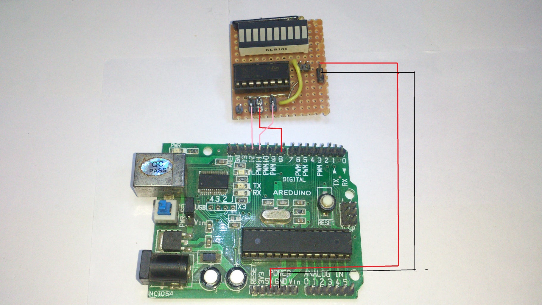
Step 6: The Main Code

Connect up the circuit as shown. Then upload the given code which can be used to control individual pins of the registers. This code is specifically designed to control relays. They may also be used to make a large LED chaser you just need to change the code based on the application.
Firstly I will explain the fundamental lines that need to be changed depending on the number of Shift Registers. The line of code that has
//How many of the shift registers - change this
#define number_of_74hc595s 1
As the name suggests you should provide the number of shift register modules you are using. The program is limited to a maximum of 40+ Shift Registers.
setRegisterPin(2, HIGH);
setRegisterPin(3, HIGH);
setRegisterPin(4, LOW);
setRegisterPin(5, HIGH);
setRegisterPin(7, HIGH);
writeRegisters();
This line of code is the primary function which u can use to control the pins of the shift register. The line "writeRegisters()" is the function that needs to be called inorder to send the data to the Shift Register.Suppose you need to control the 24th pin of the third shift register module then the code will be
setRegisterPin(24, HIGH);
Suppose u need to reset the pins so that all of them become low then the function will be
clearRegisters();
Finally the overall code for controlling the pins is given below and I have also attached the code for the program. So in this code the following pins are set high and can be reset by using the clear register function. I use 3 shift register modules so you got to change the code if you use 2 shift registers. If all goes well the output will be as shown in the video above. Use this basic idea you can design cool microcontroller projects.
CODE:
int SER_Pin = 11;   //pin 14 on the 75HC595
int RCLK_Pin = 8;  //pin 12 on the 75HC595
int SRCLK_Pin = 12; //pin 11 on the 75HC595

//How many of the shift registers - change this
#define number_of_74hc595s 3

//do not touch
#define numOfRegisterPins number_of_74hc595s * 8

boolean registers[numOfRegisterPins];

void setup(){
  pinMode(SER_Pin, OUTPUT);
  pinMode(RCLK_Pin, OUTPUT);
  pinMode(SRCLK_Pin, OUTPUT);


  //reset all register pins
  clearRegisters();
  writeRegisters();
}


//set all register pins to LOW
void clearRegisters(){
  for(int i = numOfRegisterPins - 1; i >=  0; i--){
     registers[i] = LOW;
  }
  writeRegisters();
}


//Set and display registers
//Only call AFTER all values are set how you would like (slow otherwise)
void writeRegisters(){

  digitalWrite(RCLK_Pin, LOW);

  for(int i = numOfRegisterPins - 1; i >=  0; i--){
    digitalWrite(SRCLK_Pin, LOW);

    int val = registers[i];

    digitalWrite(SER_Pin, val);
    digitalWrite(SRCLK_Pin, HIGH);

  }
  digitalWrite(RCLK_Pin, HIGH);

}

//set an individual pin HIGH or LOW
void setRegisterPin(int index, int value){
  registers[index] = value;
}


void loop(){
  setRegisterPin(0, LOW);
  setRegisterPin(1, HIGH);
  setRegisterPin(2, LOW);
  setRegisterPin(3, HIGH);
  setRegisterPin(4, LOW);
  setRegisterPin(5, HIGH);
  setRegisterPin(6, LOW);
  setRegisterPin(7, HIGH);
  setRegisterPin(8, LOW);
  setRegisterPin(9, HIGH);
  setRegisterPin(10, LOW);
  setRegisterPin(11, HIGH);
  setRegisterPin(12, LOW);
  setRegisterPin(13, HIGH);
  setRegisterPin(14, LOW);
  setRegisterPin(15, HIGH);
  setRegisterPin(16, LOW);
  setRegisterPin(17, HIGH);
  setRegisterPin(18, LOW);
  setRegisterPin(19, HIGH);
  setRegisterPin(20, LOW);
  setRegisterPin(21, HIGH);
  setRegisterPin(22, LOW);
  setRegisterPin(23, HIGH);
  writeRegisters();
  delay(500);
  clearRegisters();
  setRegisterPin(0, HIGH);
  setRegisterPin(1, LOW);
  setRegisterPin(2, HIGH);
  setRegisterPin(3, LOW);
  setRegisterPin(4, HIGH);
  setRegisterPin(5, LOW);
  setRegisterPin(6, HIGH);
  setRegisterPin(7, LOW);
  setRegisterPin(8, HIGH);
  setRegisterPin(9, LOW);
  setRegisterPin(10, HIGH);
  setRegisterPin(11, LOW);
  setRegisterPin(12, HIGH);
  setRegisterPin(13, LOW);
  setRegisterPin(14, HIGH);
  setRegisterPin(15, LOW);
  setRegisterPin(16, HIGH);
  setRegisterPin(17, LOW);
  setRegisterPin(18, HIGH);
  setRegisterPin(19, LOW);
  setRegisterPin(20, HIGH);
  setRegisterPin(21, LOW);
  setRegisterPin(22, HIGH);
  setRegisterPin(23, LOW);
  writeRegisters();
  delay(500);
  clearRegisters();
}
Attachments
Step 7: LED Chaser for Fun!!!
If you have reached this test you have successfully completed the modules. So lets make a LED chaser just for fun and also for understanding the codes working even more. The code is given below to experiment with your new modules. I uploaded a video of my LED chaser.
CODE:
int SER_Pin = 11;   //pin 14 on the 75HC595
int RCLK_Pin = 8;  //pin 12 on the 75HC595
int SRCLK_Pin = 12; //pin 11 on the 75HC595

//How many of the shift registers - change this
#define number_of_74hc595s 3

//do not touch
#define numOfRegisterPins number_of_74hc595s * 8

boolean registers[numOfRegisterPins];

void setup(){
  Serial.begin(9600);
  pinMode(SER_Pin, OUTPUT);
  pinMode(RCLK_Pin, OUTPUT);
  pinMode(SRCLK_Pin, OUTPUT);


  //reset all register pins
  clearRegisters();
  writeRegisters();
}


//set all register pins to LOW
void clearRegisters(){
  for(int i = numOfRegisterPins - 1; i >=  0; i--){
     registers[i] = LOW;
  }
  writeRegisters();
}


//Set and display registers
//Only call AFTER all values are set how you would like (slow otherwise)
void writeRegisters(){

  digitalWrite(RCLK_Pin, LOW);

  for(int i = numOfRegisterPins - 1; i >=  0; i--){
    digitalWrite(SRCLK_Pin, LOW);

    int val = registers[i];

    digitalWrite(SER_Pin, val);
    digitalWrite(SRCLK_Pin, HIGH);

  }
  digitalWrite(RCLK_Pin, HIGH);

}

//set an individual pin HIGH or LOW
void setRegisterPin(int index, int value){
  registers[index] = value;
}


void loop(){
  for(int i = 0;i < numOfRegisterPins;i++)
  {
  setRegisterPin(i , HIGH);
  Serial.println(i);
  writeRegisters();
  delay(70);
  clearRegisters();
  }
  clearRegisters();
  for(int i = 24; i > 0; i--)
  {
  setRegisterPin(i , HIGH);
  writeRegisters();
  Serial.println(i);
  delay(70);
  clearRegisters();
  }
  clearRegisters();
}
Well I have finally reached the end of this tutorial. I had lots of fun making these modules and I hope so did you. I look forward to your comments and feedback. Till next time bye!!


