

Introduction: 3D CAD Non-Animated Tutorial - Feature #1 - Revolve - Basics


-
Among the many 3D CAD programs, We will be demonstrating how to use a program called Alibre Design for this 3D CAD Tutorial, presenting the Revolve feature.
Other Programs will be introduced at some time in the future.
The first Tutorial will use a series of images grouped to supplement the text instructions in a set of 11 steps from beginning to end to create a simple Cerial Bowl.
You will be introduced to launching Alibre Design, strating a Part Workspace, setting up some basic conditions to make sketching easier, and then proceeding with sketching a basic outline of the Bowl, followed by some editing of the sketch and adding of fillets to smooth the shape, adding color and reflective elements, and saving the file.
Please continue to the next step to begin learning 3D CAD Modeling with Alibre Design.
Note! Due to unidentified issues with images & sizes - The displayed images in the instruction steps in this tutorial don't seem to show at the correct width of 652 pixels and are 'squished' so as to sometimes be unreadable. You might want to see the original html for this if you want to see the images at full size.
Step 1: 3D CAD Non-Animated Tutorial #1 - Revolve - Launch Program

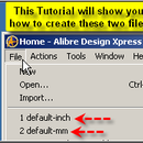
First Launch Alibre Design
Then click on the New Part icon in the Alibre Design Home Window and open a new part workspace.
Step 2: 3D CAD Non-Animated Tutorial - Revolve - Setup


Next - From the main menu, select Tools > Options > Grid;
Set Spacing: X=0.050, Y=0.050,
make sure Display Grid, Snap to Grid, are checked.
Click OK.
Step 3: 3D CAD Non-Animated Tutorial - Revolve - Start Sketch


Next - Activate Sketch Mode (Select 'Activate Sketch' Icon from Sketching Toolbar with mouse, and Click).
Select 'Line' with mouse, and Click.
Line Icon will be displayed at (Beside)Cursor,
Note: The Status Line provide relevant Hints as you move and select activities,
(Line starting hint shown).
Click on Origin to begin Sketch.
Step 4: 3D CAD Non-Animated Tutorial - Revolve - Start the Bowl Base Sketch


Now - begin placing the line to outline the shape that will be revolved to create the basic bowl shape.
First - (After Clicking at the Origin), move right (Positive) until the cursor
is at Length: 1.250, Angle: 0 (Also - See Status Bar Hints: 1.250, .00), double Click.
Then click on 'Zoom to Fit' Icon at the top of the workspace to make viewing your work and the grid easier.
Now, at the right end of this line (1.250, .00), click to continue using the line,
drag a line down (Negative Y) 0.100" (2 grid squares),
then to the right (Positive X) 0.100" (2 Grid Squares), giving a 45 Degree Line,
the cursor will display Length: .141, Angle: 315.000°, Double Click.
To give some more room to see what you are about to sketch next, select the 'Pan' function
and click beside the line so far created, and drag it down and to the left
until the Origin is near the lower left corner of the workspace.
To continue the line, Click the 'Line' icon again, or you may choose to use the menu selection:
Using the Mouse, from the main menu, Select 'Sketch' > Figures > Line.
At the lower right end point of the last line, click to continue the line, moving right 0.100"
(2 grid squares), the cursor will display Length: .100, Angle: 0, Click.
Now move right 0.500" (10 grid squares), and up 0.100" (2 grid squares),
the cursor will display Length: .510, Angle 11.310° and Double Click.
Step 5: 3D CAD Non-Animated Tutorial - Revolve - Continue Sketching Bowl


With 'Line' Still selected, Click on the end of the last line,
and drag a Vertical Line up 2.250", the cursor will display
Length: 2.250, Angle 90.000°, Click,
Again, Click on 'Zoom to Fit' to maximize Visibility.
Move Left 0.100", the cursor will display Length: .100, Angle 180.000°, Click.
Then move down 2.200", the cursor will display Length: 2.200, Angle 270.000°, Click.
Now move Left to the 'Y' Axis 1.950" to place a Horizonal Line, the cursor
will display Length 1.950, Angle: 180.000°, Click.
Finally, move down 0.150" to the Origin, the cursor will display Length: .150, Angle: 270.000°,
Double Click to end the line.
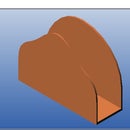
This has completed the Basic Bowl-1 Sketch outline for the Revolve.
Step 6: 3D CAD Non-Animated Tutorial - Revolve - Create Revolve


Here you will proceed to create the Revolve Feature to create the actual Bowl shape.
From the Part Modeling Toolbar on the right, Select Revolve Boss, Click.
The Revolve Boss Dialog opens, you should note that it already has inserted the 'Sketch to Revolve'
information (Sketch<1>), the default Angle for the revolve to complete (360.000°),
and requires you to identify the Axis for the revolution.
Click in the Axis field to pre-select it for accepting data.
By holding down both Left & Right mouse buttons, you enter the Rotate mode and can rotate the
view slightly to see the Y axis better. Just hold the buttons down and move the mouse slightly to the left.
Release the two mouse buttons and Click the 'Y' Axis to fill the Data field.
You should note the screen now displays a preview of the Bowl Sketch repeated in a number of Steps
to give an approximation of the finished Revolve feature, allowing you to confirm correct selections.
Click 'OK' and you will see the finished revolve.
Clicking 'Zoom to Fit' will allow you to see the whole Bowl-1 Revolve.
Clicking 'Rotate' will allow you to hold the left mouse button, and drag the mouse to see the Bowl from different Angles
Clicking 'Zoom Mode' will allow you to drag the mouse forward & backward to change the zoom level.
Step 7: 3D CAD Non-Animated Tutorial - Revolve - Editing Sketch - Begin Filleting


Now you will be shown editing the sketch to refine and smooth the sharp edges of the Bowl.
Mouse over and Select 'Sketch<1>' in the design Explorer,
Mouse - Right Click: Select Edit from the pop-up menu.
Select '2D Fillet' from the Sketching Toolbar with mouse, Click.
Set Radius to .050" (Click in 'Radius' Field, enter .050, press Shift+Tab, to accept & prepare the selection field)
Mouse over & Click Line<1>, then mouse over & Click Line<2>
(They become Red on Mouse Over, and Yellow on Clicking)
Click 'Apply'. The 'Figures to fillet' field is cleared, ready for new selections,
as the Fillet is applied and dimensioned.
Step 8: 3D CAD Non-Animated Tutorial - Revolve - Continue Editing - Adding Fillets


Now to continue to repeat this process, filleting the remaining lines.
Select the First 45° down line (Line<2>), Click
Select the Bottom Line (Line<3>), Click,
Click Apply
Click the Bottom Line (Line<3>), and Click the Secon 45° line (Line<4>),
Click Apply
Click Line<4> and the next up-sloped line (Line<5>), Click Apply
Click Line<5> and the Vertical line (Line<6>), click Apply
Click Line<6> and the top line (Line<7>), Click Apply
Click Line<7> at the inside top edge, and the vertical inside line (Line<8>), Click Apply
Click the bottom of Line<8> and the inside Bottom Horizontal line (Line<9>), Click Apply
on the Fillet Figures Dialog, Click Close.
Step 9: 3D CAD Non-Animated Tutorial - Revolve - Editing Sketch - Appearance


Now that you have completed editing the sketch by adding Fillets to all the sharp corners,
there are some things you can do to clean up the appearance of the sketch.
First - Click 'Orient to Front'on the Orient View toolbar,
You will see the many Constraint Symbols. These can be removed from the display:
Click 'View' in the main menu, Click 'Sketch Display' at the bottom of this menu,
Click on 'Constraint Symbols' from the fly-out menu to De-Select it.
This cleans up the appearance of the sketch so you can see the Fillets much better.
Now - you can exit the sketch to update the Revolve Feature by either of two methods:
First - Click on the 'Select' Icon in teh View Toolbar, or
Second - Click 'Activate 2D Sketch' again in the Sketching Toolbar.
Finally - Click on 'Orient to isometric' in the Orient View Toolbar,
and scroll the center mouse wheel to set the zoom level you want for best viewing.
Step 10: 3D CAD Non-Animated Tutorial - Revolve - Adding Color and Reflectivity


Now you can add some appearance value to the finished 3D Solid Model of the Bowl.
Select Color Properties under Edit in the Main Menu, Click
Either Drag the Bar to set the Reflectivity at 20% or Highlight the value field and enter 20%
You will notice in the preview window - the Reflection is displayed.
Click the Color Button to open the Color Dialog,
Because of the Dark background colors, select a Light Color for the bowl,
I chose a Cyan or Turquoise color. Click 'OK' to accept the color and close the Color Dialog.
Click 'OK' in the Color Properties Dialog to accept these Color and Reflection Settings,
When the Dialog closes you will se the Bowl showing the selected Reflective and Color properties.
Using what you have learned about Rotate, and Zoom, and Views,
go ahead and check out the bowl from different angles to see the effects.
Step 11: 3D CAD Non-Animated Tutorial - Revolve - Saving the Finished Model


Now - your are ready to save the finished Bowl-1 3D Solid Model!
To save the new 3D Model, Click on File in the main menu,
then Click on Save As. (Or - using the keyboard - Ctrl+Shift+S)
In the Save As Dialog, first click a directory folder from the list,
and if you want to save your CAD Tutorial models together - create a new folder,
(If you have not yet) to save them in. I chose a folder name of Alibre-Tutorials.
Name the file 'Bowl-1' and Click 'OK' to save.
Notice the activity displayed in the Status Line at the lower left as this is done.
You will see the name at the top left of the Part Workspace change from 'New Part (1)' to 'Bowl-1' upon completion of the save.
Congratulations!
You have competed this 3D Solids Model of a common breakfast bowl!
Feel free to [mailto:cad_crew@hotmail.com?subject=Completed-Animated-Bowl-1-Tutorial_at-Instructables! send us an email] letting us know!


