

Introduction: 3D Printed, Bluetooth Controlled, Arduino Robot Arm - LittleArm 2C


The LittleArm 2C is a 3D printed desktop Arduino robot arm that was made for STEM and hobby. The arm is actuated by microservos and is controlled by an Arduino Nano with a Meped Board.
This tutorial is a variation of the assembly manual for the Littlearm 2C basic kit.
Step 1: Parts List
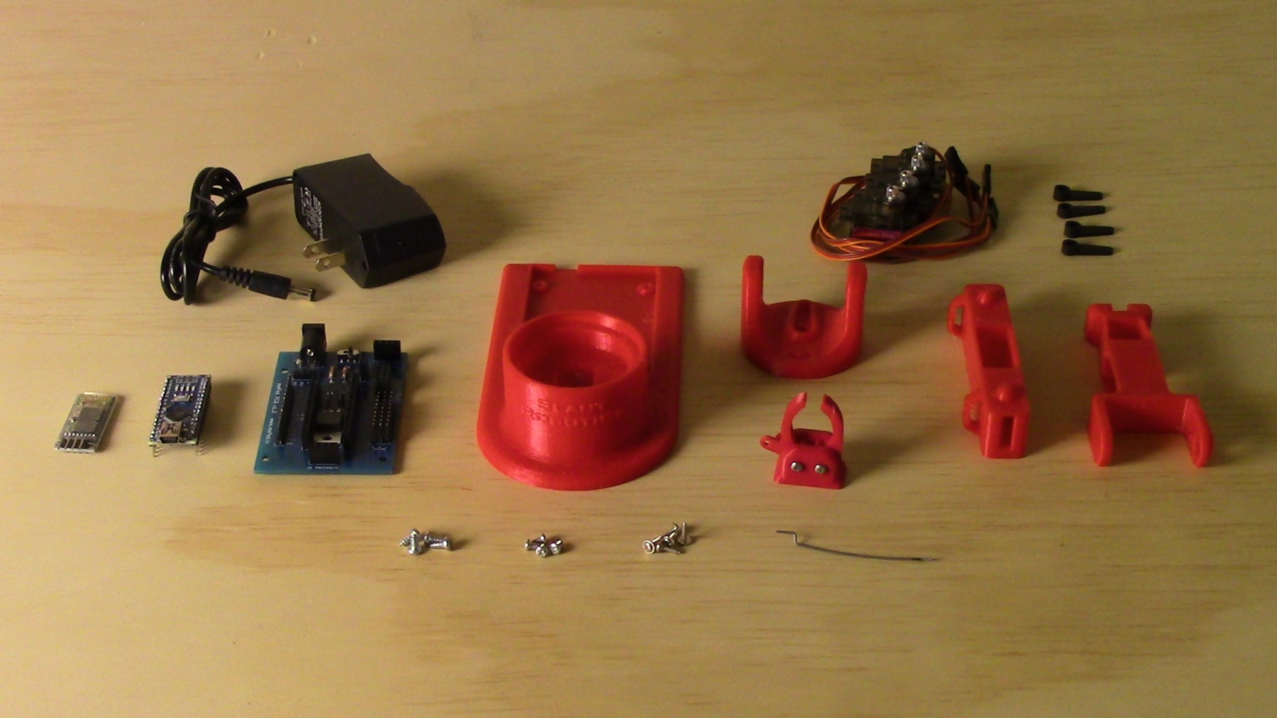

All of the parts for the LittleArm can be purchased from the LittleArm website as a package or from most hobby retailers.
Step 2: Download and Print the 3D Files

If you building the LittleArm entirely from scratch, then go ahead and download the files from here. You do have to purchase the core files for the arm, but grippers, and peripherals are all free downloads.
Note: Some peripherals may need to be scaled 10x when entered into your software.
Print the files using your preferred settings, though the lowest resolution (300 microns) is perfectly acceptable.
Step 3: Assemble Base Servo


- Insert Servo into Base so that wire feeds out rear slot.
- Secure the Base Servo with two servo mounting screws.
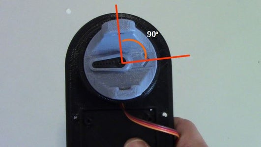
Step 4: Attaching Shoulder


- Use a spare Servo Horn to rotate the armature of the servo fully clockwise. Note: Perform this step gently as servos can be damaged from rapid forced rotation.
- Place a Servo Horn into the slot on the shoulder piece.
- Fit the Shoulder piece onto the Servo in the base so that the arrow on the Shoulder points approximately 90 degrees to the right, with respect to the Base.
- Use a horn mounting screw to secure the shoulder to the Base.
- Gently rotate the shoulder so that the arrow points forward.
Step 5: Insert Servos Into Upperarm


Press two servos into the upperarm so that their wires face and feed out the available slots. Note: If the servos are to difficult to insert, remove one sticker from the side of the servos.
Step 6: Feed Wires Through Organizing Loops


The location of the top Servo in the arm is denoted by the word “Top” on the Upperarm. Feed the wires of this servo through the organizing loops.
Step 7: Attach Upperarm to Shoulder


- Use a Spare horn to rotate the lower servo armature fully clockwise.
- Insert a Servo Horn into the shoulder slot on the Shoulder Piece.
- Insert a Servo Mounting screw into the second hole from the end of the horn and secure it to the shoulder.
- Hold the Upperarm horizontally and start the lower servo armature into the hole of the Servo Horn.
- Press and twist the Upperarm into position in the shoulder. If it does not set into the servo horn rotate slightly so that it can bind.
- Secure the horn with a Horn Mounting Screw.
- Gently position the Upperarm Vertically.
Step 8: Prepare the Forearm


- Insert a Servo into the Forearm so that the wire faces and feeds out the available slot.
- Run the wire through the organizing loops on the Forearm.
Step 9: Attach Gripper Palm to Forearm


- Start two Servo mounting screws into the palm of the gripper assembly
- Center the palm on the end of the Forearm and secure the screws.
Note: Orientation of the palm is irrelevant
Step 10: Attach Gripper Fingers


- Place the Servo Actuated finger on the side of the servo. Secure with Gripper Pin screw
- Place regular finger symmetrically to the Servo Actuated Finger and secure with Gripper Pin Screw.
Step 11: Attach Forearm to Upperarm


- Use a spare servo horn to rotate the Upperarm upper servo armature fully counter-clockwise.
- Snap the Forearm onto the Upperarm by starting the servo armature in the hole on the Servo Horn side of the forearm. Then twist and press the forearm onto the rotation Nub. Forearm should rotate freely.
- Position the Forearm in its lowest position relative to the Upperarm.
- Attach and secure a servo horn in the depression on the Forearm.
Step 12: Connection Gripper Actuation Servo


- Use a spare servo horn to rotate the Gripper Servo, in the Forearm, fully clockwise.
- Remove the horn and insert the Gripper actuation wire into the second hole from the end of the horn. Note: Insert the wire from the inside side of the Servo Horn.
- Insert the other end of the Gripper Actuation Wire into the hole of the Actuated Gripper Finger. Note Come in from the top of the finger.
- Attach the horn so that it holds the gripper open.
- Secure horn with Horn Mounting Screw.
Step 13: Organize Servo Wires

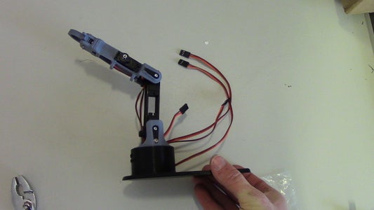
- Feed the wire from the gripper servo through the organizing loops on the Upperarm.
- Ensure that all wires feed underneath the Upperarm and out the back of the Shoulder toward the circuit area of the Base.
Step 14: Insert Nano Into PCB


Insert the Arduino Nano into the location in the center of the Meped Board so that is USB port points towards the switch on the Meped Board. Ensure all pin enter the headers on the board.
Step 15: Attach Board to Base
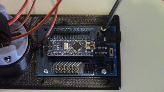

Attach the Meped Board to the Base using the 4 Arduino mounting screws. Ensure that the switch of the Meped Board is at the Rear of the Base, with the power port facing out.
Step 16: Connect Servos to Board


Plug in the servos according to the diagram. Note: To determine which lead goes to which servo compare lengths of the leads. The shortest is the Gripper, then Elbow, then Shoulder. The longest lead belongs to the Base.
Step 17: Flash the Arduino

Download the LittleArm2c_Sketch.ino from the Downloads Page of the LittleArm site and upload to the Arduino Nano using the Arduino IDE
Note: If you purchased the arduino as part of a kit from LittleArm, then it is already loaded with the Arduino code and you may skip this step.
Step 18: Plug in the Bluetooth Module


Insert the Bluetooth module into the headers on the Meped Board labeled “Bluetooth.” Make sure the pins align according the Table below.
Note: You will not be able to upload the code to the Arduino if the bluetooth module is plugged in. So be sure to perform this step after the Arduino has been flashed.
Step 19: Download Apps


Download Windows Software
- Go to www.littlearmrobot.com
- Navigate to Resource→Downloads
- Click on the button “Download Latest Windows Software Package.” A Zip folder will automatically start to download.
- Extract all files from the Zip folder.
- Ensure that your Littlearm is connected to your Computer by USB. Note: Software will no run unless Littlearm is connected.
- Click on the .EXE file in the extracted folder. Name will be similar to “Littlearm_GUI_V#.#.exe”
- The Application should open and you may begin using the Littlearm.
- Note: On the first connection it is recommended that you leave the Littlearm unpowered until you successfully connect the software. This can prevent accidental jumps and reactions of the arm.
Download Android App
- Go to www.littlearmrobot.com
- Navigate to Resource→Downloads
- Click in the button “Download Android App.”
- Download the application from the Google Play store to your Android Device.
Step 20: Plug in and Use
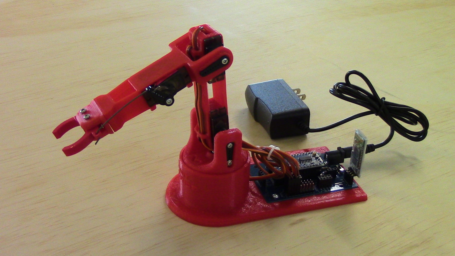
Plug in the Power Supply and start using.
Enjoy the LittleArm, your own desktop robot arm


