

Introduction: 3D Printed MITX Computer Case

This is a mostly tool-less mITX computer case designed to be 3D printed in ABS with the build volume of the Rostock MAX v2 specifically in mind. Certain parts WILL take up almost the entire build area of a Rostock MAX v2, so if attempting to print with a different printer, first verify that the build area is at least as large. The case is designed to be as compact as possible while having a modular exterior so that, should you desire, you can easily personalize it or modify the entire look of case. And speaking of modifying the case design, there is one part (Case Front) that will need to be modified slightly before printing to ensure proper fit of the front IO panel and power switch parts you purchase.
DISCLAIMER: I have yet to print this myself. Although I've done my best to give everything the proper clearances, tolerances and thicknesses for strength, the only parts I've been able to print and test are the snaps. As such, I CANNOT GUARANTEE that everything works as intended, though I have spent a considerable amount of time trying to ensure that it does.
To get started, you'll need to download all the parts in stl format attached to this instructable. To complete the build and have a working PC you'll need the following PC parts, hardware and tools:
- mITX Motherboard with compatible CPU and RAM
- Power Supply (PSU) with dimensions: 150mm x 86mm x 140mm (I used the Corsair CX600M as reference)
- PCIe Video Card (potentially optional)
- Power Cable with a low profile C13 right angle connector
- C14 Male Plug 3 Pin Power Inlet (optional if you don't mind the power cord dangling out of the case)
- Front USB and Audio IO (something like https://www.amazon.com/2-Port-Microphone-Desktop-...
- Power Switch (I like the look of https://www.amazon.com/WerFamily-Indicator-stainl...
- SSD and/or Hard Disk
- 80mm Case Fan
- Drill, small drill bit, screwdriver, (for motherboard mounting screws, front IO panel and power inlet), 3 spade connectors and a crimping tool (for connecting the power inlet to the PSU cord), screws for mounting motherboard and power inlet.
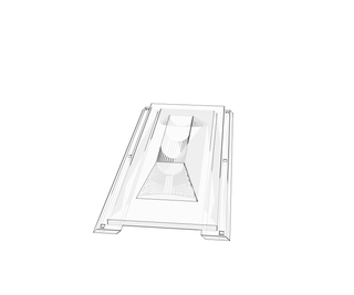
The first thing you'll need to do is print off the Case Frame and clean up the (hopefully) small amounts of support structure. Almost everything snaps or screws onto this, so like most parts in this build it's probably best to print it with a high infill percentage, if not completely solid.
Attachments


Step 1: Installing the Motherboard


Once printed you'll need to drill holes for your motherboard mounting screws in the 4 motherboard mounting points. Snap the rear IO panel cover that comes with your motherboard into the inside of the Case Frame, then slide the motherboard in and screw it into place.
TIP: Install the CPU and RAM installed before you screw in the motherboard.
Step 2: Installing the Power Supply


Next you'll need to print off the Power Supply Retainer. It consists of 4 legs which each snap into the Case Frame on each corner of the PSU, and a cap which snaps onto all of the legs and clamps the power supply to the Case Frame.
Place the PSU in its location in the Case Frame with its fan pointing towards the grill and its power socket facing up. Then snap the Power Supply Retainer legs into each recess at each corner of the PSU.
Next snap the Power Supply Retainer cap on top with the 2.5" drive bays to the right side of the PSU. Make sure each of the legs has snapped firmly into place into both the cap and the Case Frame.
Step 3: Hooking Up Power Supply


This next step requires some light electrical work. If you're not comfortable working on wiring capable of carrying wall current or would simply like to avoid this step, you could easily choose NOT to install the power inlet, and simply thread your right angle C13/5-15 power cord through the hole for the power inlet. For those that don't want the cord to dangle out of the case, continue with the following.
Now that the PSU is firmly in place, drill two holes for the screws that will hold the power inlet to the back of the Case Frame. Then screw the power inlet into the Case Frame. Plug your right angle power cable into the PSU, size up the length of cable you'll need to reach the power inlet and cut off any excess. Crimp on the spade connectors and connect them to the power inlet (it is VERY important to get the polarity right). You may also want to wrap the connections in an electrically insulating covering, such as shrink wrap or electrical tape.
TIP: Now is also a good time to thread the motherboard and CPU power cables from the power supply through the holes provided in the Case Frame and plug them into the motherboard (not illustrated).
Step 4: Installing Storage Drives

It's time to install any storage drives you might want to use, as depending on the size of the video card you install, it may get in the way of plugging in any more modular power cables into your PSU. There are slots in the Power Supply Retainer for one 3.5" drive and two 2.5" drives. The 3.5" drive simply slides or snaps into the large bay on the front of the Power Supply Retainer, while the 2.5" drives slide back into the slots on the right hand side. Once in their respective slots make sure to plug them into both the PSU and motherboard (not illustrated).
Step 5: Installing Video Card


Next, if you need to, plug the modular power cable for your video card into your PSU. Then install your video card into your motherboard, making sure that the video card's output ports and retaining tab slide into the slots in the Case Frame.
Then you'll need to print off the Video Card Retaining Clip, which you'll press into the rear of the Case Frame, in the slot where the video card's retaining tab is sitting, to prevent the video card from moving.
Don't forget to plug in your video card's power cable from the PSU (not illustrated).
Step 6: Installing Rear Exhaust Fan


Next print off the 4 Rear Fan Clips. Either place the fan over the exhaust grill on the inside of the Case Frame and snap all 4 Rear Fan Clips around the outside, or install the 4 Rear Fan Clips and then snap the exhaust fan into place, whichever is easiest. Plug the fan into either your motherboard or PSU (not illustrated).
Step 7: Installing the Case Top


Print the Case Top and the 32 Clips. The Case Top has recesses for 6 of the small clips and the Case Frame has matching recesses. Insert the clips into either the Case Frame or Case Top and then snap the two parts together.
Step 8: Installing Case Front


DISCLAIMER: The aforementioned modifications happen now!
The Case Front stl file will need to be modified slightly to ensure that the IO panel and power switch you purchase fits properly. If you purchase a similar IO panel to the one I chose you'll have to unscrew the IO card itself from the metal mounting bracket that it comes attached to. The three mounting points for the IO panel and the holes for the ports may need to be re-positioned and resized before Case Front is printed. Once Case Front is printed, you'll need clean off the scaffolding/support structure (unavoidable on this part unfortunately), drill out the mounting holes for the IO panel and install it and the power switch. Next insert the 4 clips in the corners of the Case Front or Case Frame and snap the two together. With the Case Front attached, don't forget to plug the IO panel and power switch into the motherboard (not illustrated).
All the computer components are installed. Time to finish up!
Step 9: Installing Case Base


Print off both halves of the Case Base. The two halves are designed to overlap a bit, so after you insert the 6 clips into their recesses in either the Case Base or Case Frame make sure you fit the two halves together as you install it.
Step 10: Installing Case Sides


Print off both Case Right Side and Case Left Side. Insert 6 clips into the recesses in each side and install them both onto the Case Frame.
Step 11: Complete

Tada! You're Finished!
Your next step is to enjoy your exquisitely designed case, marvel at its beauty, be awe-struck by it's practicality, and amazed at its complete lack of flaws of any kind*.
*Lack of flaws still not guaranteed.
Step 12: Further Reading on the Design

I've added this step just to explain some of my design decisions on the case, and specifically the Case Frame, as it may look peculiar when observed without considering the constraints imposed on it.
My goal at the start of the design was to see if it was even possible to design a reasonably simple, small mITX computer case that could easily be printed on a desktop printer and assembled with minimal additional hardware. The parts of a PC that really dictate the size of the case are the motherboard and video card unit. Even on their own these dictate a pretty big build volume, especially when considering a full size gaming video card. When a power supply big enough for that video card is also considered, the dimensions of the case push the limits of what desktop printers have to offer. Luckily the Rostock MAX v2 has a tall cylindrical print volume capable of fitting a motherboard-videocard unit on its end with a power supply stacked on top and even leaves some room to spare for designing a case frame around it.
I wanted to minimize any scaffolding/support structure that was printed to make assembly easier and keep waste material down, so that meant keeping any overhanging structure short and most holes small. I wanted to minimize additional hardware, so I decided to try 3D printed clips/snaps to attach parts to the Case Frame. There also needs to be room to install some fairly large parts and the case needs airflow to keep those parts cool, so that means big openings.
The result I came up with is that the back face of the Case Frame, with its large motherboard and video card IO holes (sized to spec, and scaffolding free), is printed flat and a large stiff solid face is printed vertically from it that the motherboard and power supply will mount to. Also printed vertically from the back face are two long thin spars that reach all the way to the front of the case. These serve as snap locations for the exterior panels of the case while leaving large openings for component installation and airflow. They aren't connected at the front of the case (as that would require piles of scaffolding) or supported in any other way. While they may initially be somewhat fragile, each exterior panel that gets snapped on will increasingly brace each spar.
Another benefit of all the exterior panels being snap-on, is that each is completely customizable, provided they still have locations for each snap. Should someone want locations for an extra fan, to do away with my silly handle, extra venting in the top, or a total redesign of the exterior geometry, it's all possible as long as the surface that mates with the Case Frame remains unchanged.
Speaking of the handle... I didn't want to trust the six small friction fit snaps to carry the weight of the entire case, so I designed the right, left and front panels of the case to overlap the edges of the top panel. When lifted by the handle this should allow the weight of the case to be borne not just by the 6 parallel snaps in the top panel, but also by the 16 perpendiular snaps in the side panels.
That's all I can think of right now. Any other questions?

Participated in the
3D Printing Contest 2016


