

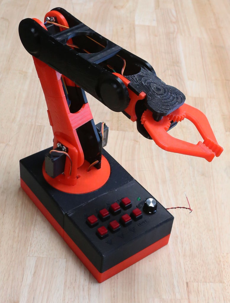
Introduction: 3D Printed Robot Arm

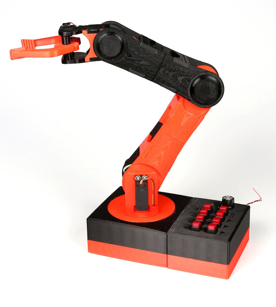
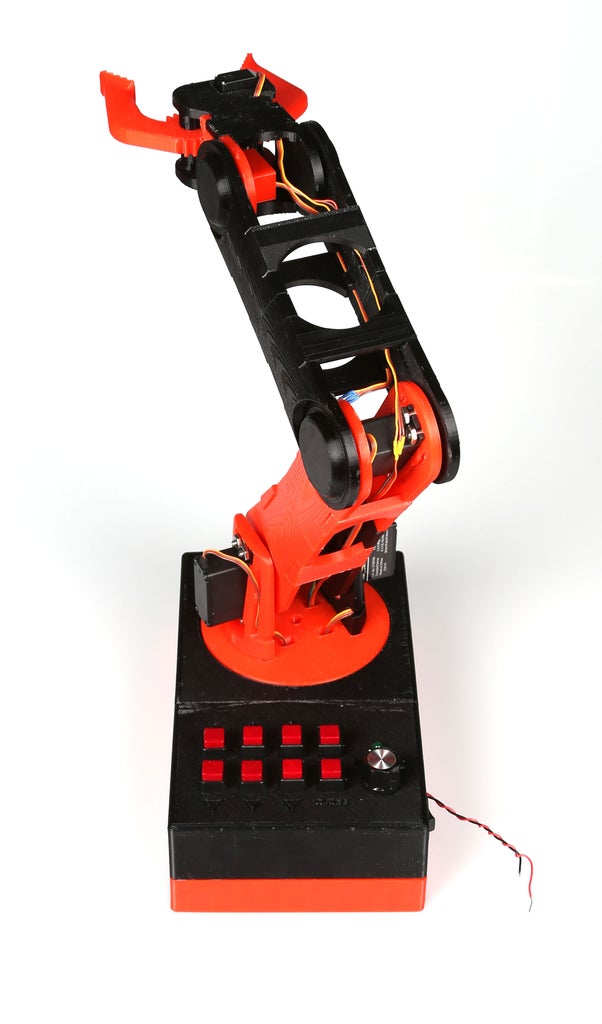

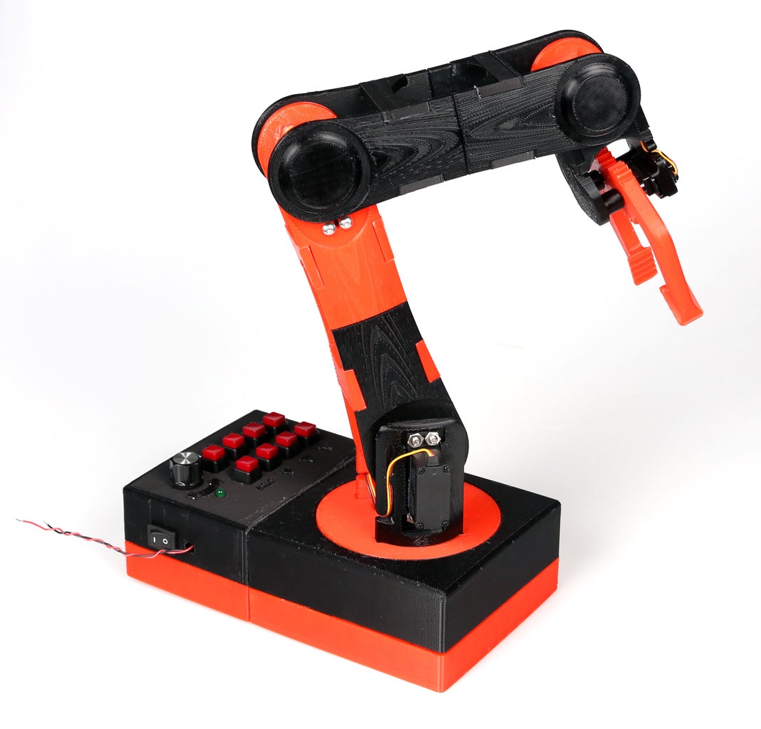


This robot arm is made almost entirely of 3D printed parts that snap together. It has three servo-controlled joints, plus a rotating base and gripper. The arm is controlled by a series of buttons that connect to an Arduino Uno hidden in the base. A simple circuit makes connecting the servos and buttons to the Arduino easy and makes set-up and assembly very quick.
Materials:
- Arduino Uno - RadioShack 276 128
- Standard servos (4x) - RadioShack 273 766
- Micro servos (2x) - RadioShack 273 765
- Momentary push buttons (8x) – RadioShack 275 1566
- On/off switch - RadioShack 55050508 (web only)
- Potentiometer and knob (specific resistance doesn't matter) - RadioShack 271 215 and RadioShack 274 416
- Green LED - RadioShack 276 022
- Printed circuit board - RadioShack 276 149
- 10K Ohm resistor (8x) - RadioShack 271 1335
- 220 Ohm resistor - RadioShack 271 1111
- Various wires and connectors
- Nuts and bolts (16x 8-32, 1/2” long)
- Afinia 3D printer - RadioShack 277 181
- 1kg roll of PLA filament - RadioShack 277 163
- power supply, capable of 2A (I used a standard bench supply for prototyping, so something like RadioShack 550 57676 (web only) or RadioShack 22 507 should work although you will need to regulate the voltage before sending it to the Arduino and servos)
Step 1: Print the Parts


The arm is about 20 inches long, so it takes a lot of time and material to print. The parts are sized to fit on the bed of the Afinia H479 printer, and some can be printed together on the same platform to save time. I used a resolution of 0.25mm and hollow fill for all the parts (other settings were set to the defaults). In addition, I found that I needed to use a raft to both help the part adhere to the print platform and help the printer compensate for my table, which was not perfectly level.
The total estimated print time for the arm is about 32.5 hours, although as mentioned earlier some parts can be printed together (the estimate was done using the print preview function of Afinia's software - my actual print time was difficult to calculate because I was still iterating through designs). Including the raft material, it uses 842.8g of filament, which means it can be printed from one 1kg roll.
Most of the parts have "flat" sides that should face the platform (see images). Many of them also have fairly delicate tabs for holding the cables, so take care when you remove the raft and support material. Study the stl file first to get an idea of where the most delicate areas are.
EDIT: I forgot to include one of the parts in the zipfolder, so I added it separately.
EDIT #2: Since people have been asking, the original Inventor files are now uploaded as well.

Step 2: Arduino Code

While you wait for parts to print, work on uploading the code and soldering the electronics.
The Arduino code for controlling the servos is very straightforward. The joints and gripper servos are controlled by a pair of buttons that increase or decrease the servos' positions by one step. The base is connected to a potentiometer that is mapped to its rotation. Depending on the order in which you wire your buttons, you may need to adjust the pin numbers in the code
I recommend testing the code with your servos to make sure that their limits are consistent with those defined in the code. Testing them after the arm is assembled could damage or break it.
The same physical setup can be used with different code if you wish to have your arm do simple automated tasks. (note that there is no positioning feedback, so the accuracy of the arm is limited by the accuracy of the servos)
Attachments
Step 3: Extend the Servo Cables

Since the servos will be positioned at various points along the arm, the cables need to be extended. Simply cut the cable and solder in an extension between the servo and the connector.
Servo position, Extension length, Number of servos
Base, none, 1 standard servo
Lower joint, 5 inches, 2 standard servos
Middle joint, 10 inches, 1 standard servo
Upper joint, 15 inches, 1 micro servo
Gripper, 18 inches, 1 micro servo
Step 4: Make More Cables

Next, make two sets of cables for connecting the circuit board to the Arduino. The servo signal cable has male headers at both ends, each with 6 pins (one per servo). The button signal cable also has male headers at both ends, but they have 8 pins each (one per button). In addition, at one end separate two of the pins from the other six, as they will be plugged in on the opposite side of the Arduino.
Step 5: Build Circuit Board


The circuit board for the arm is mostly a method for efficiently routing the various wires and signals, rather than a way of adding more components. Start with the resistors, then the various connectors (note that some of them are female and some male). Finally, solder in the connections.
Step 6: Build the Gripper


Once you have your parts, you can start assembly. Begin by pushing the microservo (with the longest extension cable) into the gripper base and route the cable through the channel. Attach the 4-prong horn to the microservo and rotate it to where you want the most "open" position for the gripper to be. Push on the claws, making sure the gears mesh. Push the other microservo into the side of the gripper and assemble the rest of the gripper. The top of the gripper has pins that help hold the claws in place, and may require a small amount of sanding to fit easily (try not to force them, as they may break off).
Set aside the assembled gripper.
Step 7: Build the Lower Segment


Now build the lower segment of the arm.
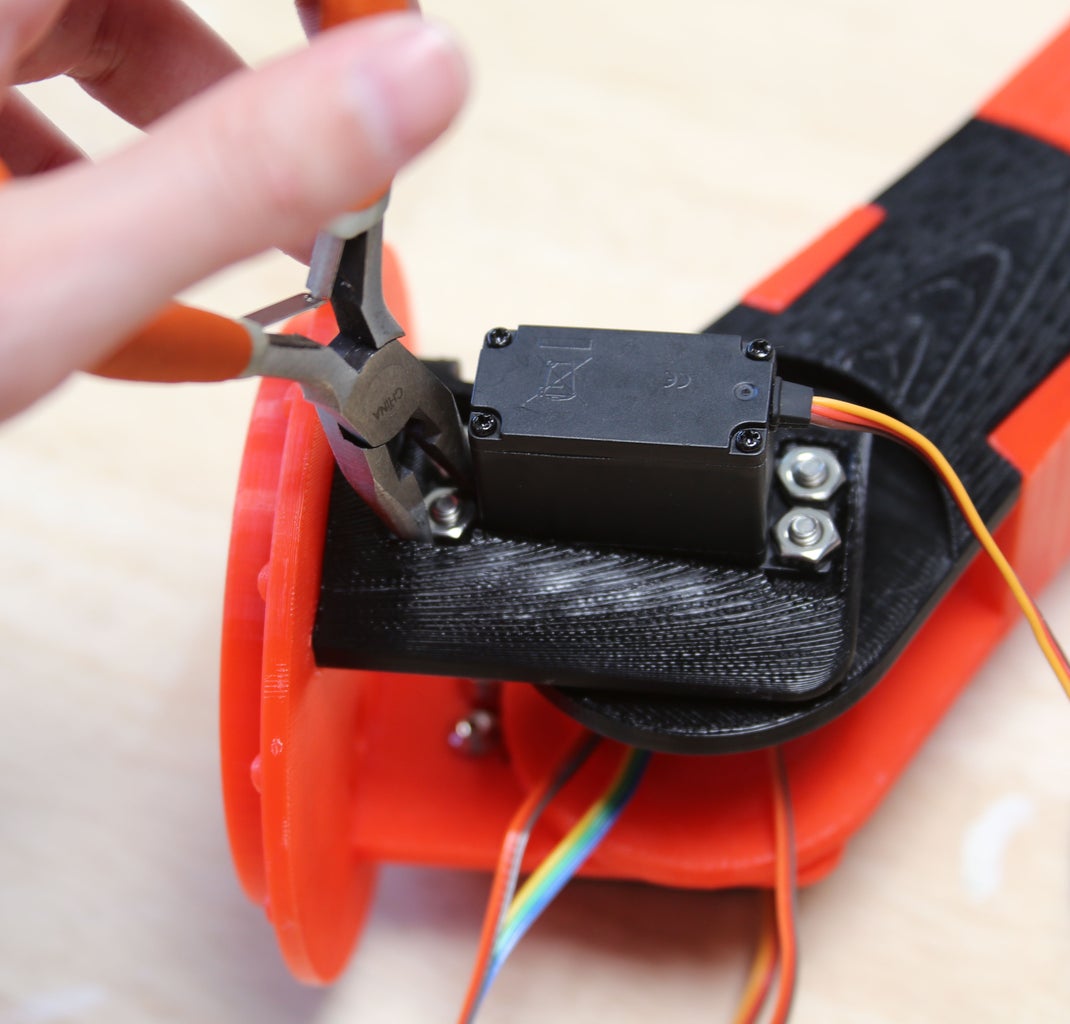
Match the long parts of the arm segment together by their cable channels and push them together. Snap in the 4-prong servo horns, making sure they are pushed all the way to the back. Bolt the servo to its mount, checking that the bulk of the servo is on the interior of the arm segment (see photos). Connect the two halves of the lower segment together using the small braces. The thicker braces go on the side of the segments with the servo horns.
Step 8: Build the Middle Segment


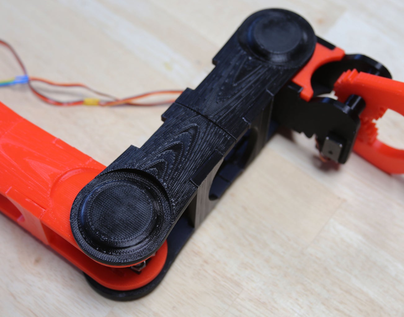


Assemble the long sides of the middle segment in the same way as the lower segment, including the servo horns. On the gripper, rotate the upper joint's microservo to one of its limits and push it into the microservo horn, keeping the parts at approximately 90 degree angles. Do the same with the middle joint servo. This will align the servos so that their limits are symmetrical and the joints have a good range of motion. Attach the braces to one side of the middle segment for stability.
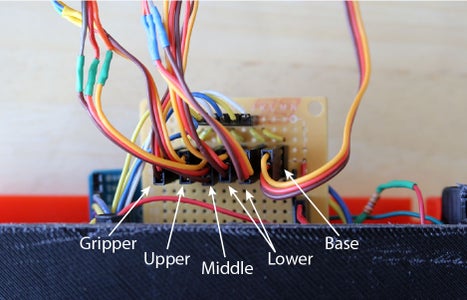
Step 9: Route the Cables


Starting on the still-open side of the middle segment, gently push the cables into their channels and under the tabs. To make sure that there is enough slack for the moving joints, rotate the part so the cable is as far from the channel as it can be and loosely clip in the cable. Continue to route the cables, carefully removing (and then replacing) braces if necessary to reach the clips. If you use a tool to help clip in the cables be careful not to pinch or accidentally cut the wires.
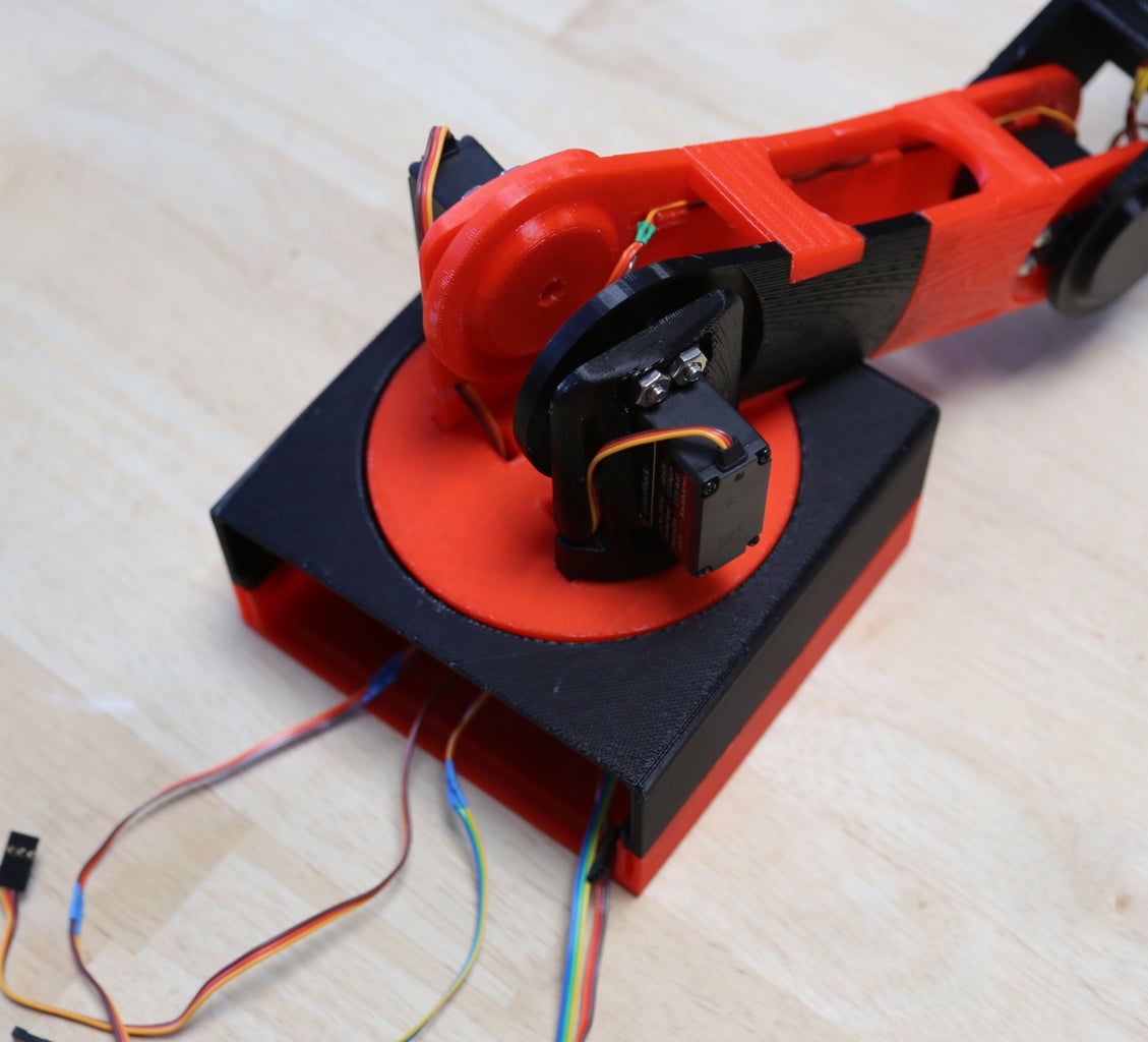
Step 10: Attach the Arm to the Base


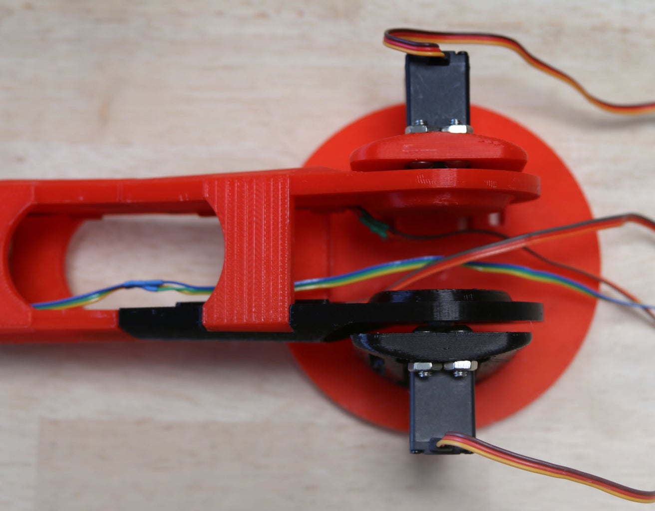

Attach one standard servo to a servo mount and place both mounts in the rotating base. Place the top two bolts for the second servo in the mount, but do not add the servo. Rotate the mounted servo so it is at one of its limits and gently slide in the arm and press on the servo horn. Push the second servo (rotate it to its limit first) into the other horn and secure it using the remaining bolts. Thread the servo cables through the holes in the rotating base.
Step 11: Build the Base


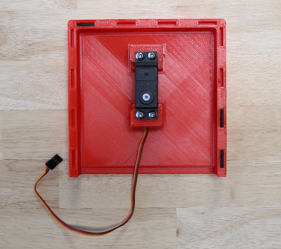

Push the final servo horn into the bottom of the rotating base (in my case, the black circular part). Sandwich the top of the base (the part with the circular hole) between the two halves of the rotating base and snap the two halves together. The arm should now be able to rotate while being constrained by the base.
Mount the last servo (this one should have no extension cables) to the bottom of the base. Make sure it is facing the correct direction. Rotate it to one of its limits and rotate the arm to match, keeping an eye on the cables. Push the top of the base into the bottom, meshing the teeth and the servo/horn. If you rotate the arm, you should hear the base servo rotating with it.
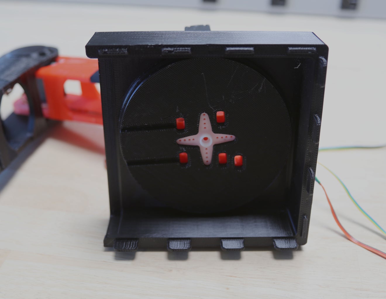
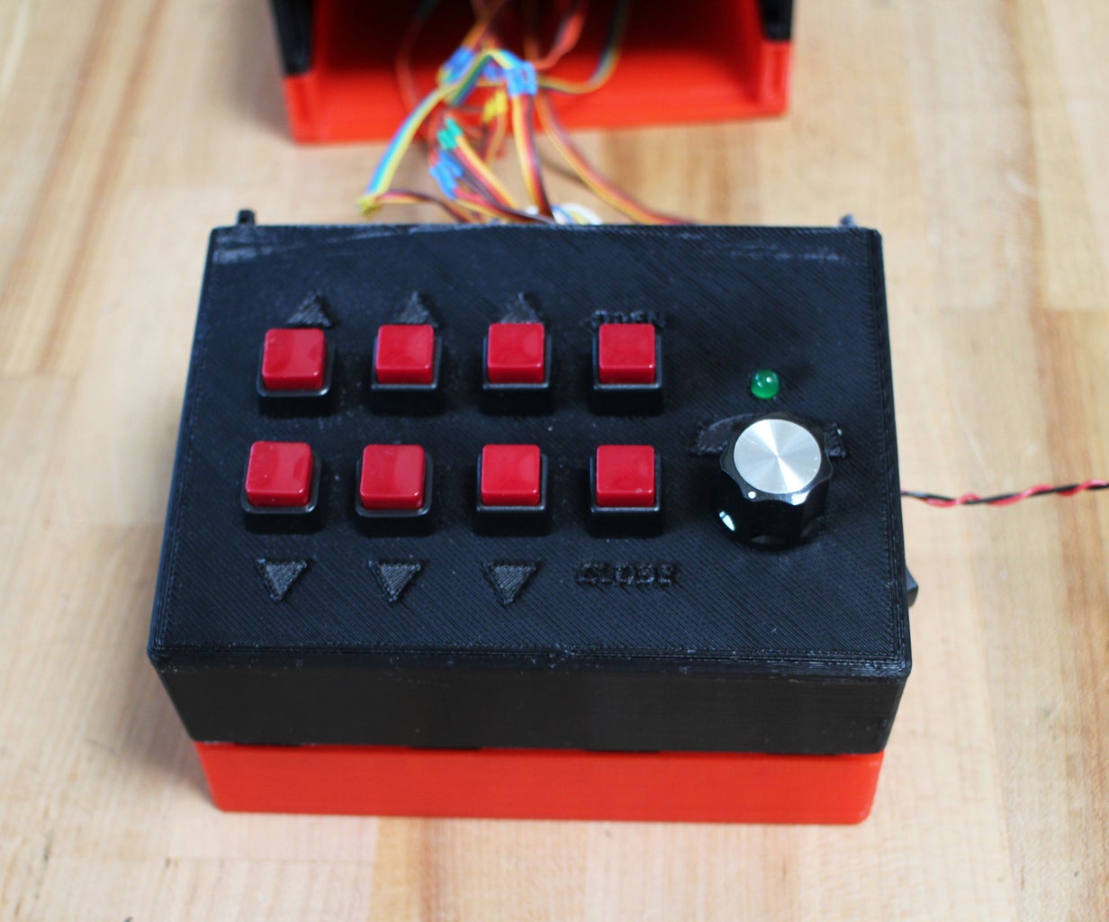
Step 12: Make the Control Panel


The control panel has 8 buttons, a potentiometer, an LED, and an on/off switch. It's easiest to solder leads to all the parts before attaching them to the base (color code the wires: red = power, black = GND, anything else = signal). In addition, add a 220 Ohm resistor to the end of the LED's positive lead.
The buttons and potentiometer I used were threaded and I was able to bolt them around the base. The LED and on/off switch both press-fit into the base. Feed one of the switch's wires out the hole in the side and twist a black wire around it (this black wire will supply ground for the circuit). Once the parts are inserted, attach the knob to the potentiometer.
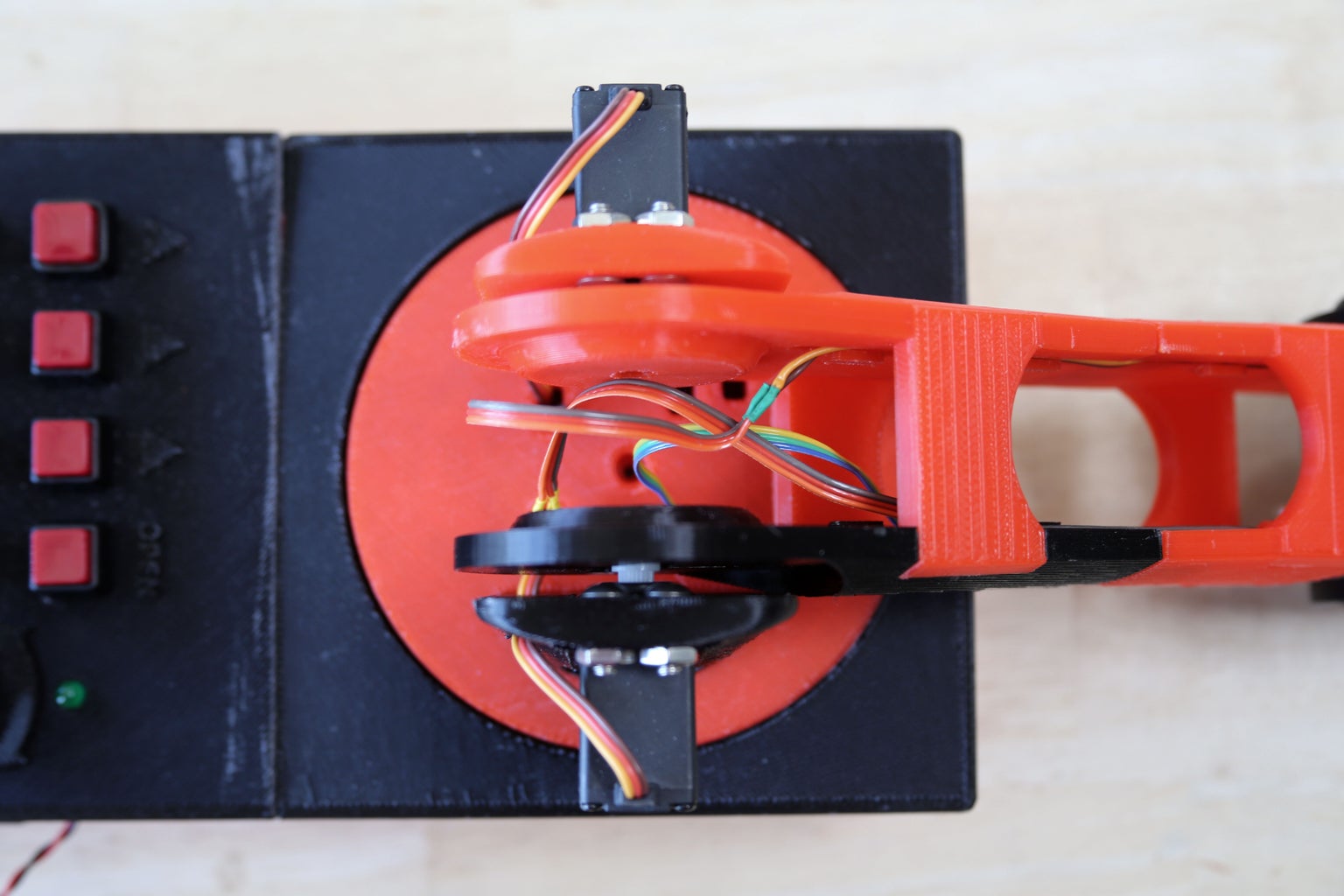
Next, bundle some of the wires together. The 5V power lines from the buttons will all be powered from one pin on the circuit board. The 8 signal lines should be soldered to a male connector - use a logical order to keep track of which button is which (see the photo for the order I used).
Step 13: Add the Circuit


At this point simply plug the cables from the control panel into the circuit. The header goes to the row of female connectors just under the resistors (the one below that will go to the Arduino). The 5V from the potentiometer and the buttons go to the 5V headers. Ground from the potentiometer, the LED, and the black wire go to the GND headers.
Step 14: Plug in the Arduino and Servos

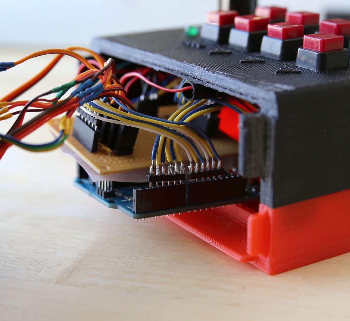
Using the cables you made earlier, plug in the Arduino. The buttons go to pins 2-7 and A3, A4. The servos signals go to pins 8-13. The power for the LED goes to the 3.3V pin, and the wiper of the potentiometer goes to pin A0.
The plugs from the servos go to the male headers at the top of the circuit board. (see photo)
Test the code at this point - be careful, the arm will "jump" awake and might hit something (aka you). Check that the servos move in the right directions when you push the buttons. If necessary, update the code to reflect how you assembled the arm (some button/servo relationships may need to be reversed - just swap the button numbers in the if statements).
Step 15: Close Up the Base

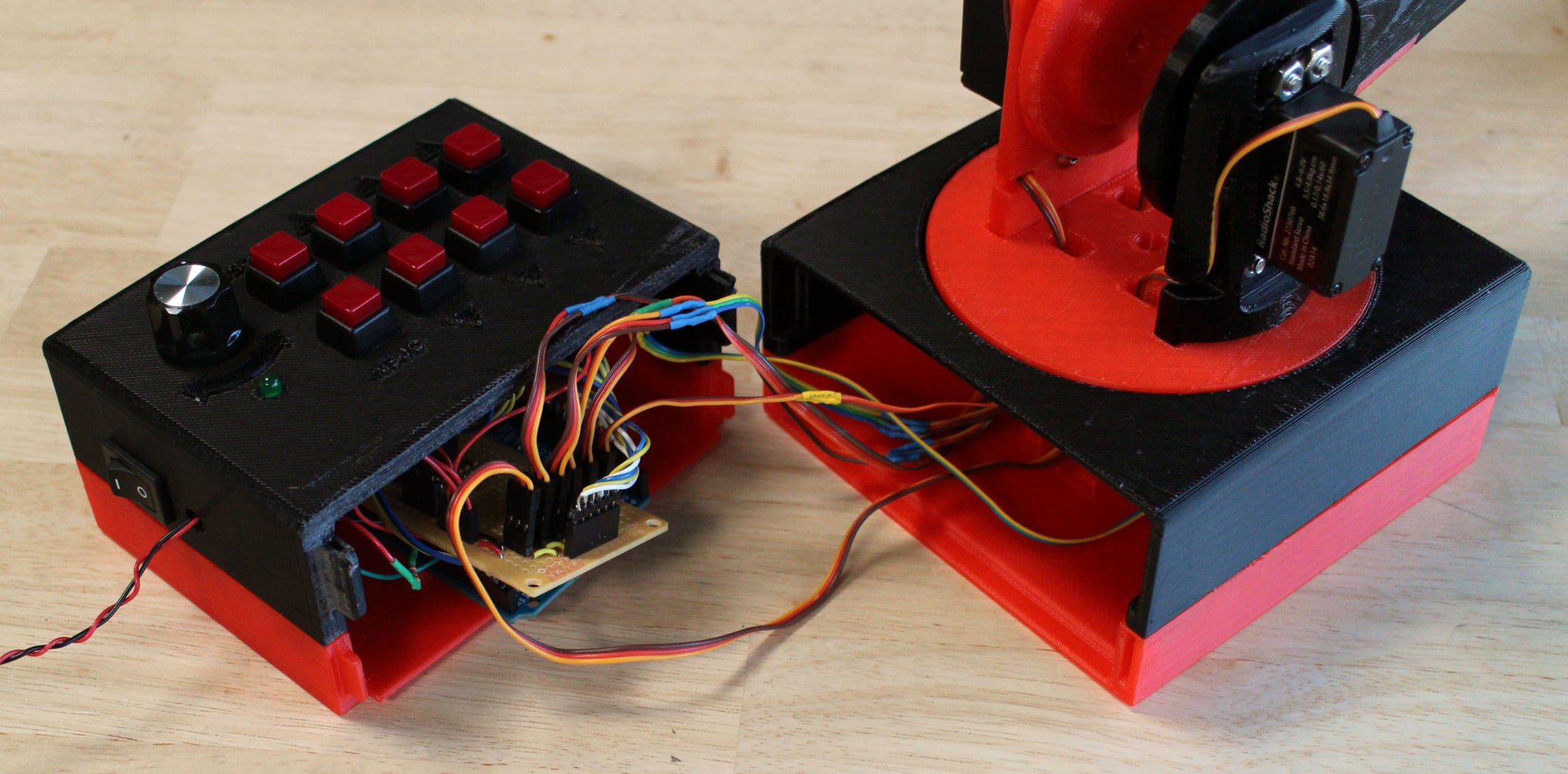


Flatten the electronics as best you can, and push the control panel onto its matching bottom part. Then close up the two halves.
Step 16: Play!


Grab your power supply, and you're ready to go! Since there are six servos, the arm pulls a lot of current (2A on start up and about 1.5A during operation).
Once you have the arm working, you can customize it by adding a different gripper or changing the code to do autonomous tasks.


