

Introduction: 3D Printed Sumo Robot With High Traction Wheels


The aim was to design and build a lightweight fully autonomous sumo fighting robot for an in University Sumo Bot competition. The robot was required to push or lift an opponent’s robot out of the arena.
Restrictions:
- Less than 1000g
- Fit within a 200mm x 200mm x 300mm (WxLxH)
- Has to be completely autonomous with zero human interaction,
- Cost under $150 AUD (not including the micro-controller)
- The robot must begin each round in the same orientation in which it was place in the measuring box.
The Arena:
The arena was circular with a diameter of 1.54m with a matt black surface and a 2cm wide white line around the perimeter.
Step 1: Components and Tools


List of materials and tools required to make the Sumo Robot:
Components:
Cost items:
2 x Motors 47:1 Metal Gearmotor 25Dx52L mm HP
1 x Motor Controller 10A H-bridge Dual DC Motor Driver Controller / High-power Strong braking
2 x Belt FingerTech Timing Belt 300mm (100T)
2 x Sonar HC-SR04 ultrasonic sensor distance measuring module
1 x Battery ZIPPY Flightmax 1300mAh 3S1P 15-25C
3 x Sticky Nano Pads
Non-Cost Items USE
Heat Shrink____________________________________________Insulation
Connecting wires_______________________________________ Interface with components
Power Switch__________________________________________ Main power cut-off
Super Glue____________________________________________Sensor mounting
ATMega128 Microcontroller _______________________________ Sumo robot controller
Female Header crimp pins________________________________Connecting sensors to controller
m3 Countersunk screws__________________________________Motor mounting
4mm bar stock_________________________________________ Wheel axles
3D printing material______________________________________For printing robot
Tools:
Scissors_______________________________________________Cut the sticky nano pads to size
3D printer______________________________________________ Print the robot
Dremel________________________________________________ Cutting the 4mm bar stock to size
Wire cutters_____________________________________________Used for multiple things
Pin crimpers____________________________________________ To crimp the femle header pins
Soldering iron___________________________________________ Make wiring looms
Hot glue gun____________________________________________ Position wires
Step 2: The Sensors


Line Sensors
The boundary of the arena is identified by a distinctive 2cm thick white line. The white line is detected using 4 digital IR line sensors.
Name: QRE1113 Line Sensor Breakout - Digital
Weight: <1g
Max Dimensions: 7.62x14mm
Interfacing Method: 3 pin interface, VCC, Output and GND.
Power Supply: 5V DC
Supply Current: 25mA
Optimal Range: 3mm
Cost: $2.95
Connection and Power:
The module is powered by 5v DC using its VCC and GND pins through the voltage regulator built into the ATMega128 microcontroller board and by the 11.1v 1300mah lithium polymer battery.
The sensor works by charging "a capacitor on the board, and then timing how long it takes to discharge. The more light that is reflected, the less time it takes to discharge the capacitor." (bildr) Therefore, the sensor can simply interface with the microcontroller through a single digital input pin.
Ultrasonic Sensors
For object detection ultrasonic sensors were chosen for their ability to detect objects in close proximity as well as from the full diameter of the arena (~1.5m). The ultrasonic sensors selected are lightweight, simple to interface with and inexpensive.
Name: HC-SR04 Ultrasonic Range Sensors
Weight: 8.2g
Max Dimensions: 45x20.6x15 mm (WxHxD)
Interfacing Method: 4 pin interface, VCC, Trigger, Echo and GND.
Power Supply: 5V DC
Quiescent Current: <2mA
Effectual Angle: <15°
Ranging Distance: 2cm – 500 cm
Resolution: 0.3 cm
Cost: $2.58
Connection and Power:
The HC-SR04 Ultrasonic Range Sensor is powered by 5v DC using its VCC and GND pins. This power is delivered through the voltage regulator built into the AtMega128 microcontroller board and by the 11.1v 1300mah lithium polymer battery.
The HC-SR04 interfaces to the microcontroller through its Trigg and Echo pins. Each of these pins are connected to one of the digital IO pins of the microcontroller. An electrical connection schematic is given later.
Acquiring a range reading involves the following process:
1. 10μs pulse is sent to the trigger pin
2. Ultrasonic sensor outputs eight 40 kHz ultrasonic pulses
3. Detects the echo back.
4. Measured distance is proportional to the Echo pulse width
5. Distance calculated by the formula: Distance = ((Duration of high level)*(340m/s))/2
6. If no obstacle is detected, the Echo pin will give a high level signal for 38ms
This process is repeated each time a sensor reading is required. The AVR C code is given later.
The ultrasonic sensors have been positioned for maximum effectiveness and coverage. Each sensor has a detection angle of 15° from its centreline each way. The maximum range of the selected ultrasonic sensor is 5 meters, due to the size of the arena this was limited in software to only look for objects within a 1.4 meter range.
Step 3: Motors, Motor Controller and Microcontroller


Motors
Speed
The target speed of the sumo robot was 1m/s.
Using the equation, Speed = distance/time , the robot covers the diameter of the arena, minus the length of the robot, in just over a second. This speed is ample for the robot to catch opponents and evade when necessary.
Torque
The major factors with determine tour pushing power is your robots motors and traction.
The motors I selected were 47:1 Metal Gearmotor 25Dx52L mm HP from Pololu.
The wheels were custom made super grippy wheels discussed later.
Traction
To generate the maximum traction from the motors, a belt drive system is used between the front, center and rear wheels. This addition tripled the contact area with the arena floor, resulting in a greater pushing power.
Motor-Controller
The motors were controlled using PWM, enabling variable motor speeds. The controller is capable of supporting voltages from 6v to 36v and a continuous current of 10A (peak 60A). It consists of two half-bridge driver chips and low resistance N-channel MOSFET’s. The two half-bridge driver chips make losses due to the MOSFET switching minimal.
The control pins on the motor controller include 2 direction pins, one for each motor, when high the motor spins forward and when low motor spins backward. It also contains 2 PWM inputs, 1 for each motor, which take a 1kHz to 100kHz pulse frequency to control the motor speed. Setting the PWM pin to low applies the breaks to the motor for stopping.
To make this sumo robot small the excess PCB on the end of the motor controller had to be cut off with the Dermel, making its overall length shorter.
Microcontroller
The microcontroller used was the ATMega128, programmed in C using AVR studio 5. This microcontroller has a 16Mhz processor, and a large number of IO ports which is sufficient for interfacing with and controlling the sumo robot. However an Arduino, or RaspberryPI could also easily be used.
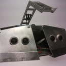
Step 4: The Robot Design
The Sumo robot was designed in a 3D computer aided design software, incorporating all of the sumo robot’s components. This allowed the design to be easily altered and manipulated to take full advantage of the size and weight restrictions.
A simple and effective design was created with a basic ramp at the front to get underneath the opponent and reduce their traction.
I only had access to a 3D printer with a printing area of 140mm Cubed, therefore the robot has been printed in a couple of separate parts.
The positioning of the internal components within the chassis can be seen in the above images. The wheels have been positioned so they protrude back past the rear of the robot, which allows for continual traction if accidental mounting of another robot’s ramp occurs.
Due to the differential drive system, the bot is capable of on the spot turning when the wheels are spun in opposite directions . Therefore the effective turning radius is 0.
CAD models of the robot components are supplied at the end of this instructable.
Step 5: The Wheels


The wheels have been designed to give the robot minimum ground clearance and maximum traction. A 34 tooth 3mm pitch GT2 pulley was modeled and incorporated into each wheel.
Two different bore holes were designed, circular and "D" shaped.
The "D" shaped ones were designed to fit snugly onto the motor output shafts and the circular ones fit over the 4mm axles.
Print Quantity:
2 x Wheels with "D" shaped bore
4 x Wheels with circular shaped bore
Complete 3D models will be given at the end of this Instructable.
Steps in making the wheels:
Step 1: Print and clean up the wheels
Step 2: Cut the sticky nano pads into 20mm wide strips
step 3: Liberally apply superglue to the part of the wheel which would make contact with the ground
Step 4: Peel the plastic layer off the cut sticky nano pad and wrap around the wheel
Step 6: Rewrap the plastic layer around the sticky nano pad on the wheel
Step 7: Tightly wrap electrical tape around the plastic layer to press the sticky nano pad onto the printed wheel
Step 8: Wait 5 minutes, then using scissors trim excess sticky nano pad from the outside and inside of the wheel
Step 9: Leave for 1 Hour
Step 10: Unwrap the wheel and you now have a super grippy sumo wheel
NOTE: It should be noted that many sumo competitions do not allow these type of 'sticky' wheels, so make sure you check your competition rules.
Step 6: Printing, Assembly and Wiring


To Print:
1 x Main Chassis
1 x Ramp
2 x Ramp Ends
2 x Wheels with "D" bore
4 x Wheels with straight bore
1 x robot roof panel
4 x axle retention rings
To Cut:
4 x (4mm bar) at 47mm lengths
Assembly Process:
After everything is printed, cut and cleaned up the assembly process can begin.
- Place the motor controller in the base of the robot as shown in the above image.
- Fasten the motors onto the chassis
- Press a 4mm axle into each of the straight bore wheels
- Put the "D" bore wheels onto the motors
- On one side, place the belt around the motors pulley and position one of the straight bore wheels in the furthest wheel position, making sure the belt is firmly around both pulleys
- Insert the center wheel
- Repeat for the other side
- Place microcontroller into the robot
- Place the ultrasonic and line sensors into the robot's ramp
- Wire up the robot as per the wiring diagram above
- Glue the ramp onto the front of the robot, making sure it is positioned as close to the ground as possible
- Put the top on the robot
- Now code the robot as you desire
Step 7: Programming
Attack Mode
A reactive approach to programming the AI into the robot was found to work best. The goal for the Autonomous Attack mode is to push the opponent out of the arena, while remaining within the arena. The sumo robot scans for objects using its ultrasonic sensors. Once an opponent is found the robot rotates until the opponent is visible in its two front sensors. Next, it rams forwards and tries to push the opponent out of the arena. The process is then repeated if required.
Interfacing With Ultrasonic Sensors
This tutorial will guide you though how to interface with the HC-SR04 ultrasonic sensors.
Interfacing Ultrasonic Rangefinder with AVR MCUs – AVR Tutorial
Interfacing with the IR Line Sensors
The line sensors can simply attach to a digital input of the AtMega128 MCU. Then the MCU can read the sensors current state. In a similar way to Line Sensing. QRE1113 Reflectance Sensor
Interfacing with the Motor Controller
The motor controller only requires digital high/low direction signals and PWM signals. Both of which a simple to implement with the AtMega128.
Step 8: The Final Robot & 3D Printable Models


Above are images of the final assembled robot. As you can see the wheels have enough traction to stick the robot to a window!
Have fun pushing others out of the arena!
But remember, check the rules of your sumo competition. Some competitions do not allow wheels like this. If that's the case, all you need to do is substitute the sticky nano pads for elastic bands or another grippy material.
3D Files
Below are all the 3D files required to print this robot. Enjoy!


Runner Up in the
Drones Contest

Participated in the
Battery Powered Contest

Participated in the
Epilog Challenge V

Participated in the
3D Printing Contest

Participated in the
Toy Contest


