

Introduction: 3D Printed CNC Mill


Ive designed this mill so that most of the parts that are hard to get or make can be 3D printed. Its design to be modular so you can easily change the size of the machine by changing either the sides or the front and back plates. Its accurate enough to cut and drill circuit boards, and small enough to fit in the boot of your car.
Almost any good CNC software can be used, but for a beginner I would recommend Easel it is very easy to use and is plug in an play.
I used an UP printer using ABS plastic, and there is a common problem with most printers is that they print holes around 1-2% undersize, so the the holes for the bearings, bolts and nut has been drawn little oversize to compensate. I cant predict how they will fit with other types of printers or materials.
The first video is of AlexcPhoto mill he is now offering a kit so check it out on step 2
The sides and back are made with 2 layers of 3mm acrylic which can be laser cut if you have access to a laser cutter. Alternatively you could print the DXF files full size and cut and drill the material by hand.
- The finished sizes of the machine are Z axis (up down) 50mm X axis (left right) 275mm Y axis (forward back) 170mm
- Outside dimensions are 400mm wide, 400mm deep and 300mm high.
- The DXF files, some browsers have a problem downloading the file I think it a bug. Right click on the DXFand save link as should work with most browsers
Step 1: Stuff You Will Need


I use core electronics for most of the electrical items as they provide a very quick service, but Ebay or your local jaycar or radioshack should also have most of these items. The fastens from core come in packs of 10 with nuts. Some of the parts, such as the threaded rod and bright steel rod is just easier and cheaper to go to local hardware or engineering supply than to find them on the internet.
Just a note on the rods, You could use "bright" "ground" "stainless" or "chrome" rod there is a big difference in price with bright begin the cheapest and the most likely to be delivered bent, rusty and damaged, so check before you hand over you cash. If your like me and pull things apart you may be able to scavenge some of the parts to keep the cost down, chrome rod is commonly used in printers and photo copiers, and old laptop charger and a cordless drill motor also found new life in this project. In addition you will need around 520 grams of abs filament to print all of the parts.
No laser cutter or 3D printer?
If you are in the US you can purchase a kit from AlexCphoto. He has redesigned the 3D printed parts so they look a little different but the fit on the laser cut sides without modification. So have a look at his work on step 30 and Look out for his helpful tips and advise in the comment section.
Alex now has an Ebay shop so 3D printed parts are available here.
If you live in Australia PM me and I may be able to help you out
Links to the parts
10 Pcs 40 Pin Headers - Straight
40 Pin Break Away Male Header- Right Angle-10 Pcs
Breadboard-friendly 2.1mm DC barrel jack
Arduino Uno R3
Dupont Wire 20cm Female / Female 100pcs Pack
Stepper motor - 200 steps/rev, 12V 350mA
Stripboard - Large
10 sets M3 * 30 hexagonal standoffs mounting kit
10 sets M3x16 screw low profile hex head cap screw
10 sets M3x20 screw low profile hex head cap screw
10 sets M3x25 screw low profile hex head cap screw
10 sets M3x30 screw low profile hex head cap screw
DC motor You can also get these from a cordless drill or photo copier
This hardware was from ebay. Ive included images as the links can go dead after awhile
linear bearings 8mm
linear bearings 12m
Mini chuck
CNC-5mm-x-8mm-Stepper-Motor-Jaw-Shaft-Coupler
List of fastens. I’ve try to be as accurate as possible... I’m not that good at counting, But the list should be very close to the amount you need.
Some Instructable members have reported that the 3mm and 8mm brass nuts don't fit. You need to also have the correct spanner size nuts. The 3mm has a 6mm spanner size and the 8mm has a 13mm spanner size. (as measured across the flats)
- M8x1.25 Brass Nuts X 6
- M8x1.25 Steel Nuts X 62
- M8 Flat Washes X 24
- M8x1.25 Threaded rod 420mm long X6
- M8x1.25 Stainless Threaded rod 420mm long X2
- M8x1.25 Stainless Threaded rod 130mm long X1
- M3 6mm nylon stand-offs X14
- M3 10mm stand-offs X6
- M3 30mm stand-offs X18
- M3 Nuts X192
- M3 Washes X85
- M3 6mm bolts X8
- M3 10mm bolts X24
- M3 15mm bolts X44
- M3 20mm bolts X38
- M3 25mm bolts X20
- M3 30mm bolts X20
You will also need
- 12mm bright or ground bar 400mm long X4
- 8mm bright or ground bar 110mm long X2
- Laptop charger at least 4 amps again ebay can help this one works well
19V 6.3A FOR TOSHIBA PA-1121-04 LAPTOP AC ADAPTER SUPPLY CHARGER
- 10x10x10x1.6mm U channel aluminium 400mm X4
- 0.8mm x 8mm sheet metal 400mm X4
- A mulitmeter is also useful to set up your stepper motors Digital Multimeter - Basic
Some members have reported that the STL files are not working correctly, they seem to be corrupt form some servers. Try downloading the mill zip folder or getting the files from thingiverse

Step 2: Rod Clamps


Lets start with the easy stuff, hopefully this is not the first time you have used a 3D printer and your familiar with how to remove the raft and any scaffolding that is still attached.
I would recommend using the "fine" setting on the printer and the highest amount of "fill" for all the parts. Also preheat the bed thoroughly, and make sure the printer is in a warm draft free environment, especially with the larger parts as they can warp and split if cooled too quickly.
Also make sure you print the tool slide and the and the z axis with the same 3D printer. I found that would not fit together properly when printed on 2 different machines.
The 12mm rod clamps stop the rods from sliding back or forwards, and are easy to print and remove the raft. Just orientate the print so the holes for the nuts face up so they don't fill up with raft.
- There are 3 spaces for captured nuts, and a 3mm screw will tighten the clamp.
- you will need 8 of these clamps
- To fit the captured nuts on all of the parts it can be useful to fit a long bolt in from the back, screw on the nut and then push the nut into position with pliers.
Attachments

Step 3: Bearing Holders


The bearing holders are also easy to print and the raft comes off easily. Most printers print holes around 1-2% under-size so the the hole for the bearings has been drawn little oversize to compensate. I use an UP printer and the bearings fit perfectly, and can be pressed in with your thumb or a pair of pliers. I cant predict how they will fit with other types of printers or materials.
- The bearings are type 608 and have an inner diameter of 8mm
- The are 4 captured nuts.
- you will need 4 of these bearing holders.
- Print with the large hole facing up.
Attachments

Step 4: Rod Holders


The rod holders are used to hold the threaded rod in place and gives the acrylic some rigidity and provides somewhere to mount the back and front of the machine. Again these are easy to print but the raft is a little more difficult to remove inside the 8mm hole.
- Print with the nuts holes facing up
- Raft inside the 8mm hole need to be removed
- There are 4 captured nuts
- You will need 12 rod holders
Attachments

Step 5: Linear Bearing Mount


The Linear bearings listed on step one have an OD of 21mm and an ID of 12mm. Just remove the raft from the mount and inside the hole and fit the bearing. I found that depending on whether my printer is having a bad day or not the bearings could either be pushed in with my thumb or had to be pressed in with the vice.
- You will need four of these mounts for the Y axis.
- The may need to press in with a vice.
- Each mount has four 3mm nuts
Attachments

Step 6: Anti Backlash Nut


The anti backlash nut is fitted to the led screws and ensures the machines accuracy, by removing any end play from the nuts that move the X Y and Z axis. I'm pretty happy how well this works and the screw on the side ensures that it can be adjusted at any time for wear. The raft is a little more difficult to remove around the slot and adjustment screw.
- There a three M3 nuts to fit, the adjustment screw nut is quite difficult to fit. I use some tweezers to hold it in place.
- The little L shaped reinforcement stops the screw punching into the plastic and can be made from offcuts of the shims used in step 6
- A good quality super glue will hold it in place.
- Use M8 x1.25 brass nuts in each end and stainless steel threaded rod to keep wear to a minimum.
- When fitting the rod loosen the adjustment screw and thread the rod into both nuts while squeezing the plastic housing together.
- After you release the housing there should be very minimal end play, if the nuts a lose on the housing remove one of the nuts and rotate 60 degrees and try again.
- The nut can be placed in 12 different positions (6 on each side) find the position that has the lest amount of end play.
- The adjustment screw can then be used for fine adjustment of the the backlash. Tighten it until the lead screw binds and then back it off a little.
- The lock nut can then be tightened.
Attachments

Step 7: Spindel Motor Mount


This is a fairly large print, I found it prints well on its side as shown in the photo, its designed to fit a 36mm motor which are quite commonly found in cordless drills and photo copiers. The motor usually come with a metal sleeve which takes the diameter up to 38mm, so make sure the sleeve is fitted to the motor, before fitting it to the mount. Jaycar electronics can also supply the motors but at the time of writing they were out of stock.
- The raft can be a little tricky to remove from the mounting holes.
- You will need to fit 2 nuts in the back of the mount
- There are 4 bolts that hold the mount to the tool slide
- 2 bolts hold the motor in place via the split mount, don't tighten these unless a motor is fitted, as the print can be broken if is bent too far
Attachments

Step 8: Tool Slide


The tool slide is one of the larger prints, so care need to be taken that the printer is hot and in a draft free environment before you start. I printed this part with the flat side down and it seemed to work well.
- Make sure the raft is completely remove from the inside of the large holes, as the bearings are a tight fit and will jam if there is raft in the way
- There are 4 nuts located under the linear bearings, to provide a mounting point for different or larger tools. you could mount a dremill on there if you wanted.
- Watch the position of the four nuts near the antibacklash nut, if the are not assembled correctly it causes a miss alignment and the tool slide will jam when fitted to the z axis. (see photos)
- Fit the 8 nuts first again using a long bolt to keep the nuts straight.
- The 4 bearings can be then pressed in.
- One of the anti backlash nuts can then also be fitted
- A revised version of the tool slide (tool side offset holes), has the anti backlash nut mounted a little lower so to provide a little more travel


Step 9: Z Axis


The Z axis is the largest and most difficult print. Print flat with the large holes at the bottom, and don't do what i did on my first attempt...."god it stinks in here and open a window" The print ended up with a few cracks in it, which I super glued, you maybe able to see the repairs in the photos. I have since printed another two, with the window closed and it work perfectly.
- The raft is quite difficult to remove so take your time, take care to remove all the raft from the holes where the linear bearing fit.
- The four little rod holder can have nuts and bolts fitted but don't tighten them until the rods are fitted as they can break.
- The X4 12 mm linear bearing can be pushed in. If they are too tight to go to be pushed in with your thumb try putting the bearing on a piece of wood and pushing the print onto the bearing.
- If the print is warped the linear bearings will bind on the shaft. Fit the two 12mm shafts the best you can and leave the print in the sun or heat it with a hair drier to release the tension on the bearings.
- One anti backlash nut can be fitted to the underside of the z axis
- Two 608 bearing can be fitted
- Its worth getting the anti backlash nut adjusted correctly before fitting.
- Use 130 mm of stainless steel rod and four steel nuts to hold everything in place.
- Use some light lubricant and wind the nut back and forth a few time with a drill, to check that nothing binds.
- you can then readjust the anti backlash nut if it needs it.
Attachments

Step 10: Fitting the Stepper Motor to the Z Axis


The stepper motors are NEMA style motor and need to have 4 wires (bipolar) and a 5mm shaft. The mounting hole spacing is 31mm and they have a 1.8 degrees step. They are quite common so you shouldn’t have any problem finding them. As you can see from the photos the shaft was a little too long so I cut them down to better fit the coupling. The tool slide was fitted here for better photo clarity, It may be easier to fit the tool slide after after the z slide is fitted to the machine.
- You will need X4 30mm stand-offs X4 10mm M3 bolts and X12 M3 washers. The stand-offs I got from core electronics have a male thread at one end. If your stand-offs don’t have this thread you will have to cut the heads off some M3 bolts and screw them into the stepper motor.
- Use X3 M3 washers on the end of each stand-offs to space the motor correctly. (you only have to use washers on this axis)
- The coupling can be fitted to the motor shaft and tighten with the Allen key.
- The Motor can them be fitted to the z axis housing using X4 10mm M3 bolts.
- There are two holes at the bottom of the housing for a screw driver to make things easier.
- The tool slide may be fitted after the Z axis is fitted to the machine.
- Finger tighten the 2 bolts through the tool slide into the anti backlash nut
- Fit the two 8mm ground rods
- Spin the lead screw a few times and then, tighten the two bolts through the tool slide.
- The four bolts holding the rods in place can then be tightened
Step 11: Fitting the Spindle Motor


The spindle motor has a shaft size of 3.17mm and a diameter of 36mm. They are quite common and can be scavenged form an old cordless drill or bought new for less than $20.00 Normally you would fit the spindle motor after the Z axis is fitted to the machine, Its shown on the bench for clarity.
- Fit the four M3 x 20mm bolts into the mount first as they can not be fitted after the motor is in place.
- The mount can be then attached to the tool slide.
- The chuck can be fitted to the motor and the Allen key tightened.
- The motor comes with a metal sleeve this needs to stay on the motor.
- The motor can be slid into the mount and the hight adjusted, and tightened.
- If you use a motor from a cordless drill the gear can be removed by applying heat to the gear.
- There is also a handy little speed controller in a cordless drill, which you can use to change the RPM of the spindle if you want.
- Make sure the motor is not excessively worn and has a rated voltage of at least 12volts and 12000 rpm
Step 12: Front and Back Plates


The front and back plates are Identical, and have 2 sheets of 3mm acrylic on each plate as that is all the laser cutter I have access to is capable of cutting. You could make the plates from any suitable material, or just cut it out of 6mm instead. If you don’t have access to a laser cutter you could print the DXF out full size, use it for a template and cut and drill the plates, side and top plate using hand tools.
- Each plate requires X8 M3x15 bolts, X8 M3 washers, X2 12mm rod holders X2 400mm long 10x10x1.5 aluminum U channel, X2 .8mmx8mmx400mm sheet metal spaces and X1 bearing holder.
- Make sure the plates are clean before you sandwich them together, as they pick up grit and dirt due to static.
- Screw in the 8 bolts with washers into the bearing holder and rod holders finger tight to start with.
- Make sure both rod holders are orientated so you can get a screw driver on the clamps later on in the build.
- Sit the edge of the plate on a straight edge and tighten all the bolts evenly.
- Drop the sheet metal spacer into the U channel and gently push the edge of the plate into the it.
- Use some super glue to help hold the U channel in place.
- Now repeat the process on the other plate, just watch orientation of the rod holders, you need to be able to get a screw driver on the clamp bolts.
The DXF files, some browsers have a problem downloading the files I think
its a bug. Right click on the DXF and "save link as", should work with most browsers.
Attachments
Step 13: Side Plates


The side plate are much the same as the end plate to assemble just remember there is a left and a right so they are a mirror image of each other. There are two different versions of the side plate short and tall. The Tall version is to build a mill that has more clearance between the tool and the deck, say if you want to carve thick materiel or box lids or if you want to use a dremill tool instead of the small motor. If you want to make your mill as shown in this instructable use the short sides. If you make it out of 3mm you will need four.
- Each side plate requires X8 M3x15 bolts,X16 M3x25 bolts X24 M3 washers, X2 12mm rod holders, X4 8mm threaded rod holders, X1 bearing holder, X2 430mm, M8 long threaded rod, X12 M8 nuts
- Screw in the 8 bolts with washers into the bearing holder and rod holders finger tight to start with.
- Make sure both rod holders are orientated so you can get a screw driver on the clamps later on in the build.
- Screw 2 nuts on to each end of the threaded rod and then slide the 8mm rod holder on.
- Screw 2 more nuts on to each end of the threaded rods.
- The 8mm rod holder can now be attached to the sides using 16 M3 25mm bolts and washers.
- Sit the edge of the side plate on a flat surface and tighten all the M3 bolts evenly.
- The threaded rod needs to be centred in the side plate, and then the four nut next to the rod holder can be tightened evenly.
- Care need to be taken so the sides don’t have tension on them after tighten the nuts. Make sure the sides remain straight while tightening.
- Now repeat the process on the other side plate, just watch orientation of the rod holders, you need to be able to get a screw driver on the clamp bolts.
Step 14: Top Plate


The top plate is very easy to assemble just remember to centre the threaded rods and and tighten them so the plate remains flat. You will need just one of these.
- Each side plate requires X16 M3x20 bolts, X16 M3 washers,X4 8mm threaded rod holders, X2 M8 430mm long threaded rod, X12 M8 nuts
- Screw 2 nuts on to each end of the threaded rod and then slide the 8mm rod holder on.
- Screw 2 more nuts on to each end of the threaded rods.
- The 8mm rod holder can now be attached to the sides using 16 M3 20mm bolts and washers.
Tighten the 8mm nut against the rod holders make sure the rods are centred and they plate remains flat
Attachments
Step 15: Work Deck


The work deck it a little tricky to assemble, three layers have to be glued together and all the bolt holes have to align perfectly.
- You will need X39 M3 nuts, X20 M3x30mm bolts, X4 linear bearing mounts, super glue, X2 12mmx400mm bright rod.
- I found it easier to work from the bottom to the top.
- Fit X4or 6 30mm bolts through the bottom sheet with the threads pointing up in the centre of each side. (These bolts will align the three plates and will be removed later)
- Fit four nuts to the bolts and drop the centre plate on top without any glue and tighten the bolts.
- When you are happy they are aligned properly remove the centre plate without removing the bolts.
- Super glue can now be spread on the bottom plate and the centre plate dropped back on.
- All the rest of the nuts can be fitted to there hexagonal holes.
- More super glue can be spread on the centre plate.
- Now the top plate can be dropped into position and 4 more nuts use to clamp the three plates together while the glue dries
- Leave to dry on a flat surface
- Once dry the 4 linear bearings can be fitted with 30mm bolts
- Fit the X2 12mm rod before tightening the mounts as this will align the bearings.
- The rods can now be removed.
- You can now print off some clamps and use 30mm bolts and flynuts to attach them to the work bed

Step 16: Assembling the Frame


In this step the machine finally starts to look like something better than a box of parts. The machine will start coming together quite quickly now
- You will need X24 M8 nuts and washers
- Start by fitting one nut and washer to the end of every threaded rod.
- The nuts need to be wound on just enough so that the washers barely touch the plastic panels.
- Next the two sides can be fitted to the top plate, and use 4 nuts and washers finger tight to secure them.
- The front and back plates can then be fitted, with the remaining 8 nuts and washers.
- leave all the nuts finger tight at this stage.
Step 17: Fitting the Lead Screw


Before fitting the bottom lead screw you need to decide if you want the stepper motor at the front or the back of the machine. I’m putting the motor at the back so I have left about 20mm of thread rod sticking out the back for the coupling to connect to.
- You will need X4 8mm nuts X1 anti backlash nut and X1 420mm stainless steel rod.
- Remember back in step 6 we put brass nuts in the anti backlash nuts, don’t be temped to put steel nuts in it, it will wear and bind very quickly. steel nuts can be used on each end of the threaded rod.
- Put the thread rod into one of the bearings and wind on the anti backlash nut about 1/3 the length of the rod.
- Now wind a steel nut on about the same amount.
- Push the rod through the second bearing and and out of the first bearing. Now fit the nut to the other end of the rod.
- The rod can now be pushed back into the first bearing, and a nut fitted to the outside. leave about 20mm of rod hanging out of one end to connect the stepper motor coupling to.
- These two nuts can be tightened up to lock the rod in place.
- When tightening the two nuts at the other end of the rod ensure there is no tension on the rod that could pull or push the end plates.
- Finally adjust the anti backlash nut, and check that the lead screw spins without binding.
Step 18: Fitting the Work Deck


The work deck is very easy to fit and will only take a couple of minutes. The two 12mm rods need to be clean free from any burs and lubricated with light oil, WD40 or similar.
- You will need X4 30mm stand-offs, X1 stepper motor, X1 coupling, X4 M3 15mm bolts, X4 M3 washers,X2 M3 25mm bolts X2 12mmx400mm bright rod
- Wind the anti-backlash nut to near the centre of the lead screw.
- The stepper motor can be fitted with four 30mm stand-offs and the coupling.
- The motor can now be fitted to either the back or front plate.(your choice) with the four 15mm bolts and washers.
- The four 12mm rod clamps should all be finger tight.
- The two 400mm bright rods can be slid in part way from the front of the machine.
- Make sure the anti backlash nut is facing up.
- The work deck can then be carefully positioned and the rods slid though the four linear bearings and into the back panel.
- Run the work deck back and forth a few times to check for binding and tighten up the four 12mm rod holders.
- Using the two 25mm bolts the work deck an be secured to the anti backlash nut.
Step 19: Fitting the Lead Screw to the Y Axis


This step is similar to the last, but if you fit the Y axis fully assembled, like I’ve done here you will have to adjust the lead screw with everything in the way. Its worth getting the anti backlash nut working correctly,as shown in step 6 first and marking the position of the nuts before you start.
- You will need X2 12mmx400mm bright rod, X1 M8x420mm stainless threaded rod, X4 M8 nuts, X4 M3x30mm stand-offs, X4 M3x15mm bolts, X4 M3 washers, X1 stepper motor, X1 coupling.
- The stepper motor can be fitted with four 30mm stand-offs and the coupling.
- The four 12mm rod clamps should all be finger tight.
- The two 400mm bright rods can be slid in part way from the side of the machine, and the Z axis carefully slid on.
The rods can then be slid through to the other panel and the 12mm rod holders tightened
You may find that the Y axis binds and doesn’t slide as nicely as the work deck, this is because the print is a little warped and has tension on the bearings. I found that the print will relax after a few days and that heat or hot sun will also help.
- The thread rod can then be pushed through the bearing and screwed into the anti backlash nut.
- You may have to adjust the anti backlash nut as shown in step 6
- Once your happy with the adjustment, screw the rod almost to the other bearing and fit a M8 nut to the end of the rod.
- Continue to screw the rod until you can fit another nut to the inside of the first bearing.
- The two outside nuts can now be fitted
- leave about 20mm of rod hanging out of one end to connect the stepper motor coupling to.
- These two nuts can be tightened up to lock the rod in place.
- When tightening the two nuts at the other end of the rod ensure there is no tension on the rod that could pull or push the side plates.
The motor can now be fitted to either the left or right plate.(your choice) with the four 15mm bolts and washers.
Step 20: Mounting the Electronics


Mounting the electronics is straight forward, with the exception of one of the screws in the arduino has to have part of the head filed down, as the mounting hole is too close to the header pins mount to the board. If your easy driver boards come without the pins you will have to solder the 9 pins as shown.
- You will need 6X M3 6mm long nylon standoffs, 10X 20mm M3 bolts and nuts, 4X 16mm M3 bolts and 12 nuts.
- File down the head of one of the 20mm bolts so that it fits flat into the mounting hole that is close to the header pins.
- Four of the 20mm bolts can be fitted to the ardunio with 3mm nuts screwed on the underside. (Not nylon standoffs as shown in the photo)
- The arduino can now be attached to the plastic electronics board with 4 nuts.
- If the easy driver came with out pins they can be soldered on the back side of the board.
- Only solder pins in the pin labeled power in - +, GRD, step input, direction input, motor coil A and motor coil B
- The 3 easy drivers can now be bolted in with M3 20mm bolts, 6mm nylon standoffs and nuts.
- The relay can also be bolted in with M3 16mm bolts, use 4 nuts on the underside of the relay as spaces to give clearance to the back of the circuit board
Step 21: Wiring Up the Eletronics


The wiring is pretty easy, use your dupont connectors and and start plugging stuff in. If your dupont connecters have female plugs at each you can use a header pin to change it to male so it will plug directly into the ardunio. First we will look at the easy driver board, many of the pins are not used in this project.
- There are four earths that need to be grounded to the arduino One on each easy driver and on on the relay. Cut 4 black dupont wires and solder them so that they are all joined. Use some shrink wrap to insulate the wires. they can now be plugged into the drivers and a GRN on the arduino
- On the lower right there are 3 pins GND (ground) STEP and DIR(direction).
- GND goes to GND on the arduino Note there are usually 3 GRN pins on the ardunio board it doesn't matter which one you use.
- On the X axis driver STEP goes to pin 2 and DIR goes to pin 5
- On the Y axis driver STEP goes to pin 3 and DIR goes to pin 6
- On the Z axis driver STEP goes to pin 4 and DIR goes to pin 7.
- Next the relay The vcc pin goes to the 5V ( 5 volt) pin on the arduino
- The relay GND pin goes to GND on the arduino
- The IN1 pin goes to pin 12 on the arduino
- cut some of the bent header pin strip 21 pins long and remove 7 of the pins as shown in the photo.
- You can now cut some strip board 30 holes wide, 5 or 6 hole deep and drill two 3mm holes for the mounting points
- Two screws and nylon spaces can be fitted and the bent header pin strip can be soldered in.
- Six dupont leads can be cut in half and soldered on the back side of the strip board.(use the same color for each stepper motor coil)
- Now 2 larger diameter wires can be soldered on the back of the 2 remaining pins for the spindle motor. the positive wire can be connected to the center screw down terminal on the relay
- The dupont wires can now be plugged into the easy drivers, and the strip board screwed down.
- The Barrel Jack can be solder on to a strip board 7x15 holes, and two mounting holes drilled.
- Screws and nylon spaces can be fitted to the board.
- 2 Rows of straight header pins can be soldered in 3pins for the positive (center pin) and 3 pins for the negative.
- A red and black dupont wire can be plugged to the barrel jack board and into each power connection on the easy drivers
- The negative from the spindle motor can be soldered on the negative side barrel jack board.
- A red wire can be soldered onto the center pin of the barrel jack and the other end goes to the left screw down terminal on the relay
- The barrel jack board can now be screwed down.
- All going well you should hear the relay click when you plug you USB cable in and start Grbl, and the easy drivers should light up when the power supply is turned on.
- If you haven't installed the software yet you might want to leave the power off for now.
Step 22: Wiring Up the Stepper Motors


The stepper motors are next. Use heat shrink to ensure the wires are well insulated as if you have a sort it could damage the easy drivers, or cause a fault that could be hard to locate later on. DO NOT connect or disconnect the stepper motors to the easy driver with the power on, it will damage the drivers.
- You will need dupont connectors, heat shrink, cable clamps and mesh cable guide .
- Use an ohms meter to identify the two coils inside the motor, you should get a resistance reading on 2 pairs of wires coil A and coil B
- I soldered the same coloured wires to each coil as it makes it easy to keep track of things. Coil A has blue dupont connectors and coil B green connectors
- First slide some heat shrink on to each stepper motor wire, and cut enough of the dupont connector wire so that it will reach the controller which is mount on the back of the machine.
- Strip the wires and solder, slide on the heat shrink and heat with a lighter or soldering iron to complete the join
Step 23: Software.


I've put a few screen shots with notes on this step, to make it a little
easier. I could not get X loader to work on my macbook so I've got the set up for windows. Once the Arduino board has been flashed with the X loader program you will no longer be able to use it with the Arduino software, however you can then use Grbl on windows or a mac. I have a few screen shoot of the Mac version of Arduino and Grbl as they are slightly different to the windows version you will need the following software
- arduino
- Grbl
- Xloader
- grbl hex file
- If you run into problems this will link you to help
- First thing to do is to plug in you Arduino board and open up the Arduino software to get the board talking to your computer.
- In the tools pull down tab you will find serial port you can choose from.
- If your not sure which one to choose, go into Start / control panel / system / hardware / device manger / ports (com & lpt) That should tell you which com port to select.
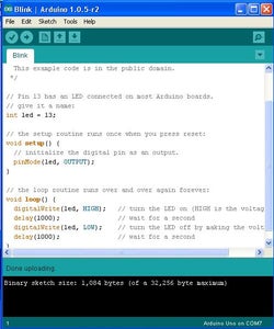
- Double check that everything is working by running a sketch. On the Arduino software file / examples / basic / blink.
- Now hit the arrow button below the "edit" tab and you should see the Aruduino board light up and a "message done uploading" at the bottom of the screen.
- Now open up Xloader and select the hex file, the device (uno) and the com port.
- Warning once you hit upload you wont be able to use the Ardunino software on that board.
- Hit upload and give it a minute or 2 until you see the upload done message.
- Now open Grbl and choose the com port
- Once you click on the open button, you should see text scroll down the page
The following is for a mac computer
- To Install Arduino and Grbl on a Mac its pretty straight forward, but the serial ports are a little differently set up
- Fist install arduino and go to tools / serial port and choose one of the ports with usb in the name e.g. /dev/tty.usbmodemfa131
- Run a sketch just like in windows to check everything works.
- Grbl will not work unless you have installed Ardunio first.
- Flash you Arduino board using xloader on a windows machine.
- Install Grbl and choose the correct serial port and every thing should work
Step 24: Grbl Settings


Now we need to change a few settings in Grbl to calibrate the machine so that everything works as expected. I have used stepper motors with 1.8 degree steps (200) steps per rotation, and a thread pitch of 1.25mm. If you have used different motors or a different pitch you will have to calculate the steps per mm, but its not too hard. Grbl just has to know how many steps per mm of movement
- First steps per rotation divided by thread pitch (200 :- 1.25 = 160)
- Next if you are using mircostepping multiply by the number of steps (160x8= 1280)
- Plug your mill in and open Grbl. Open the advanced tab, click on unlock Grbl and then Grbl settings.
- X,Y and Z steps/mm will have to be changed to 1280
- change the step pulse, usec to 30
- change default feed,mm/min to 250
change default seek ,mm/min to 500
change the acceleration, mm/sec^2 to 5.000
You can certainly play around with the settings to make you mill go faster, But I found than if you run it too fast it will lose steps. It is partially sensitive to the acceleration, mm/sec^2 setting and will miss steps badly if that setting is to high.
You can now plug your laptop charger into the machine and make sure that the tool moves in the correct direction when you use the axis control on Grbl. Remember we are talking tool direction, as the work moves on the x axis, it move the opposite direction to the arrow on the screen.
The current to the stepper motors can be controlled with the small pot on the easy drivers, if you find the motors lose steps the current can be increased or reduced if the motor get excessively hot.
Step 25: Setting Up the Easy Driver Current Control by Alexcphoto

Some Makers have a a little trouble getting the stepper motors to run reliably, Alex has kindly written up how to set the current for your motors
A-Ha,.. ok,. I found the math
and it is essentially the same as with a step stamp. What may have thrown me for a loop is that I think the easy drivers i got direct from Hong Kong off of ebay have low grade sense resistors that may not be the value they should be,.. in fact i think these are just standard resistors not sense resistors (sense resistors are supposed to be super accurate but cost a hair more)
Here is how it works. Measure resistance between the pins labeled 4 & 5 (you can also just measure RsA it’s the same trace, just in different places of the board) the key is you want the value of that resistor.
This is your sense resistor value (aka) Rs Mine measure at 0.8 ohm (according to at least two other tutorials this should be 1.5 Ohm)
Next while the board is powered up, and the motors are plugged in, place the ground probe of your voltmeter to contact 2, and the + probe to contact 1.
Now as you turn the pot the reading on your voltmeter should change, this reading is your reference voltage (AKA) Vref The last variable you need is your max current or Imax (my motors are 0.4A)
Now for some simple math. (8/Rs)*Imax = Vref (now i plug in my numbers) (8/0.8)*0.4 = 4
So if i want my current limiter to be set to 400mA (0.4A) i must turn the pot till the Vref = 4volts.
Step 26: Tool Bits


I got the bits from a seller on ebay quite cheaply and they last quite a while as long as you don't break them. Just be sure to get the right diameter shaft 1/8 inch or 3.17 mm.
I was surprised just how many different types of bit are available for that shaft size.
Step 27: Work Flow


Now you have your machine working you will need to generate some Gcode to make it do something useful. There are a number of free software packages that will get you started, Inkscape and makercam free and the shapeoko mill uses it, but I prefer to use prodesktop and Vcarve. I have done a number of instructables on using both prodesktop and Vcarve. Probably the 2 most useful are the keytag project and the sign project
I have just discovered a new online software Easel it is very easy to use and is free I highly recommend it.
The screen shots and photos have notes on them to help you
- Your Gode needs to have an .NC suffix
- This is a small machine so you may have to slow the feed rate down if the stepper motors lose steps
- Not all .NC Gcodes will turn the spindle motor on You may have to turn it on manually.
- Its worth running the machine a few times without a tool in the spindle until you have confidence that everything is working properly. (saves breaking tools)
- Remember to set the tool height and zero the machine before you start, This is the most common mistake people make.
- If you use Vcave the AXYZarcs(mm)*.nc setting works well and will turn the spindle motor on and off automatically.
- If cutting a profile (cutting through the material) put the job on top of a piece of scrap to avoid cutting the work deck.
- A user manual was kindly written by Maximium who has made a plywood version and put it on thingiverse
Attachments

Step 28: How Hard Is It to Build?


I've had a student and another instructable member motoring build a mill, and the both said they were a little intimated by this project especially the software part of it. "what if my computer wont talk to it?" But getting Grbl to work really isn't that bad.
I found the most difficult part was collecting all the nuts bolts screws wires and everything else to complete the project. Also I found removing the raft from all the pieces rather tedious.
After running the mill on a number of projects the only problem I found was the spindle motor get quite hot after more than 20 minutes of continuous use, but it still works perfectly and most jobs take less than 10 minutes.
Finally if you do make a mill, I would love to see a photo of it so hit the I made it button and Ill give you a pro membership.
Step 29: The DATTA Bulid


Recently I was invited to run a workshop for DATTA (Design and technology teachers association) and I had around fifteen teachers come and have a go at assembling a mill. We only had around three hours timetabled so unfortunately we didn't get it finished in the allocated time, but it was a great learning experience for everyone. I could see some of my instructions on the instructable needed a little tweaking, and I have since fixed that up.
Everyone had a go at removing the raft from the printed pieces and fitting bearings, motors nuts bolts, checking out the instructable and the other two machines, and at the end I think most people felt that they could build one. One of the participants struggled with the tool slide not lining up, at the time I wasn't sure what had gone wrong, after I got the machine home I discovered he had inserted a couple of nuts in the wrong position, so that is now noted in step8 of this instructable. So it was corrected and it now slides perfectly.
Enough rambling from me check out the photos
Step 30: Icare Remix


Instructables member Icare has completely redesigned just about everything, which I thought was really cool. He has done a great job of the CAD drawings and I thought I would share it with everyone. Hes changed the 3d prints to better suit his machine and so they can be printed without a raft and he is currently working on limit switches for all three axis.
Step 31: AlexCphoto Remix


Alex has redesign the 3D printed parts, and it planing on offering a kit at a very reasonable price. He has just open an ebay shop so check it out at if your chasing the 3D printed parts
He is located in Seattle, and you can PM him here AlexCphot
He has posted lots of tip and tricks in the comment section so keep an eye out for his advise.

Second Prize in the
Microcontroller Contest

Grand Prize in the
Formlabs Contest

Runner Up in the
Tech Contest


