

Introduction: 3in1 Sunglasses


In this article you will find 3 main steps concerning glasses/sunglasses:
- How to fix a broken arm by reproducing the one left.
- How to add a USB drive in an arm (first method)
- How to add a pen in an arm (second method)
Why?
I have started this project trying to fix a pair of broken sunglasses. The left arm was missing (with its screw) so I have tried to reproduce it and replace it. It has been really successful.
I then got the idea to include things in the arms. So I have designed new arms for my current sunglasses, and I have added a USB drive and a pen.
To the date of the publication, it has been almost 2 months that I am wearing my sunglasses almost everyday, and I have already used both of the USB drive and the pen many times (mostly the USB drive, but the pen has been really useful too).
How?
This is basically Computer-Aided Design (CAD): I have used Fusion 360 to design the arms, with a small help on Meshmixer.
Finally I have 3D printed the pieces.
On which glasses?
Of course it will mainly work on glasses with large plastic arms. I you try on thin metallic arms, you probably might not be able to print them.
Also it will be easier with plastic hinges (they are basically holes in the plastic with screws to hold the arms), but it will also work with metallic hinges, though the design needs to be much more precise (the first step made for fixing the arms has been done on metallic hinges with no problems).
For example it will work perfectly on wayfarers sunglasses.
If you are the lucky owner of the walking 400 sunglasses by Decathlon, you can just download and print the designs directly, because I have designed the arms specially for those sunglasses!
Materials:
- a slim USB drive.
- a ballpoint pen, with small diameter cartridge (usually 3mm for common ballpoint pens). I have used a Reynolds Medium 048 black, because the tip of the cartridge is thin, and because I like to write with this pen.
Last points before to start:
Finally, I describe here a technique that I experimented and thought to be the easiest. Once finished I ran into this video showing a similar way of designing sunglasses (extruding images from 2 orthogonal planes), but not using Fusion 360. So I decided to publish this article anyway.
And I also ran into this video that describes how to use Fusion 360 in sculpt mode. It might inspire some of you to reproduce sunglasses arm (though I think the method I explain bellow is simpler) :
Step 1: How to Reproduce an Arm From Broken Sunglasses


As I said in the introduction, this project started with a pair of sunglasses that only has the right arm remaining... Here I will explain how I have designed the left arm based on the other one. This step is organized in 30 sub-steps with one photo for each.
Before to start, make sure you have a screw that you can use to hold the arm to the sunglasses. In my case, the screw was missing, so I had to find one! Luckily I always keep every screw from the object that I disassemble, so I had a lot of choice, and I found one that was thin and long enough to fit perfectly in the hinge.

Now lets start!
- Measure the length of the remaining arm, from a specific point to another.
- Take a photo from above.
- Take a photo from one side.

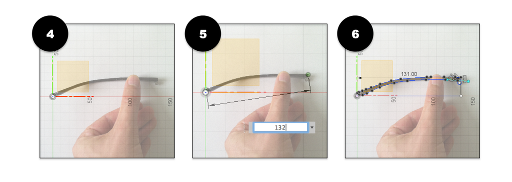
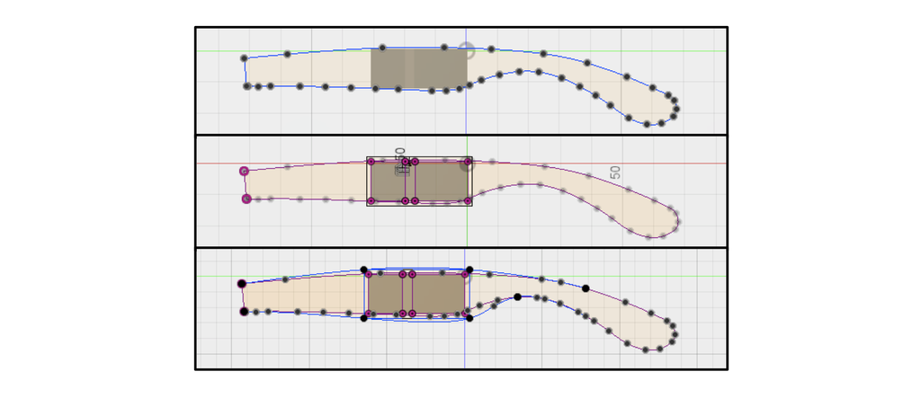
Now it is time to use Fusion 360. - Insert your photo taken from above (sub-step 2). Make sure to reduce the opacity, 50% is enough.
- Right click on the canvas you just added (in the browser on the left), and select "calibrate". Then select the 2 points and enter the values you measured in the sub-step 1.
- Create a new sketch on a plan parallel to the canvas. Use the spline tool and follow the edges of the arm.
- Then insert the second photo on an orthogonal plane compared to sub-step 4.
- Reproduce sub-step 5.
Reproduce sub-step 6.
Note: try to make the arms on the canvas horizontal, and starting at the same point. As you can see on sub-steps 6 and 9, both arms start at the same point on the left. - Extrude one of the 2 shapes you draw before (on the image I chose the sketch from sub-step 9). In "Operation", make sure "Join" is selected then click "OK".
- Extrude the other one (sketch from image 6 here), so they intersect each others.
- Then select "Intersect" instead of "Join" in "Operation", and click "OK".
- Now you have to make the hinge. In this step I have created an offset plane in between the 2 arrows in green and red (corresponding to the actual shape of the hinge).
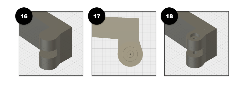
- Then using a sketch I have redesigned the ring delimiting the hinge using the "3-points circle" tool.
- And finally I have extruded (using "Cut" in "Operation") this disk on both sides up to the arrows from sub-step 13, and I have added a small offset of 0.25mm on both side (so it will fit better after printing).
- I have created another offset plane on the top of the hinge.
- I have drawn 2 rings considering the size of the screw. I made the smaller ring smaller than the screw so it can "bits" the plastic when it is placed.
- And I have extruded them just like on the photo.
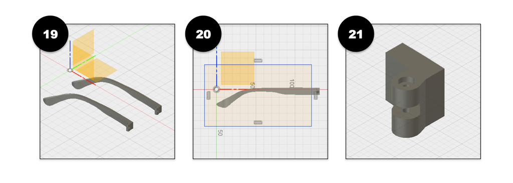
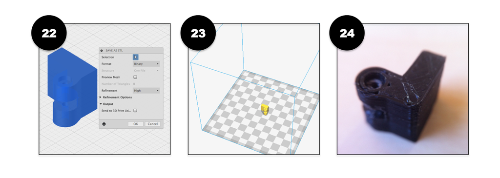
Note: Now it is almost ready. But we don't want to print everything if the hinge does not fit, or does not work properly... So from sub-steps 19 to 24, we are going to print just the hinge and try it! - Then I have copied/pasted the new arm (to save one, and modify the other one). And I have hidden one.
- I have created a big rectangle overlapping most of the arm, but leaving the hinge.
- And I have extruded it to remove the bigger part, and to keep the hinge alone.
- I have saved the file as .stl.
- I have added it in my slicer.
- Then I have printed it.
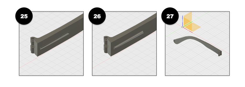
Bellow there is a gif on how the hinge works. As you can see, my first attempt did not work as expected, and the arm was not moving properly... So I went back to sub-steps 13 to 18, and tried to redesign it. And the second attempt was perfect! - Then I have added the last details on the arm to make it similar to the original arm. So I have extruded a slit on the arm's side, 0.5 mm deep.
- Then I have extruded a long rectangle in the slit, 1 mm high. And I have used the fillet tool to smooth the edges.
- Save it as .stl, and here the your arm! It is almost done! The last thing to do is to smooth the edges. Unfortunately it does not work with the fillet tool in Fusion 360. From what I have read on the internet, it is because the object has been created with spline lines (sub-steps 6 and 9).
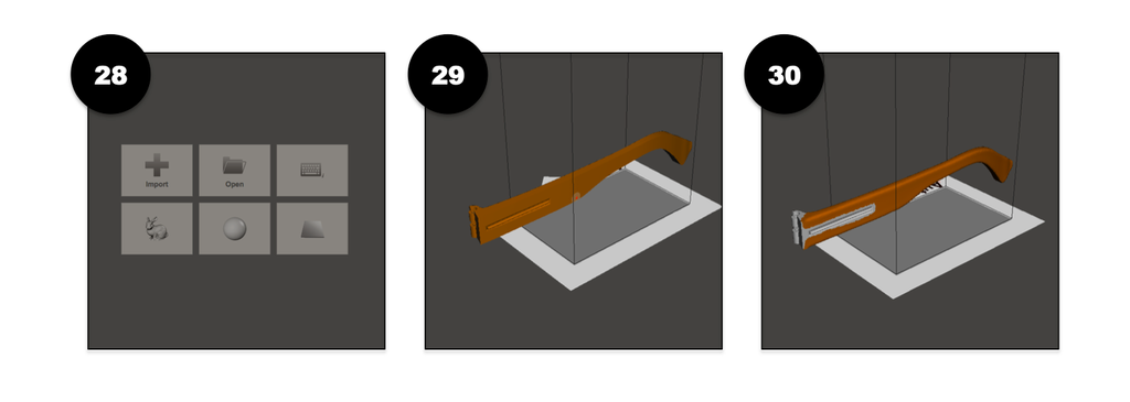
So a simple way I found to smooth the edges without trouble, was to use Meshmixer. - First I have loaded the arm in Meshmixer.
- Then I have remeshed it. To do so, just select the arm entirely (double click on it for example), then go in the "select" tab, "Edit" and "Remesh". Here I have used "Relative density", and in "density" I have set 50%. And I have done this 3 times. The remesh is important because it affects the quality of the smoothing in the next sub-step. If there are not enough meshes, smoothed edges are going to be quite rough.
- Then select the edges you want to smooth. Go to "select", "deform" and click on "smooth". Now play with the parameters to obtain the best smoothing.


 Note: try to make the arms on the canvas horizontal, and starting at the same point. As you can see on sub-steps 6 and 9, both arms start at the same point on the left.
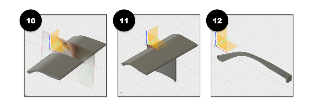


You can now export it as .stl and print it!
Congratulation, you made it! Bellow is an image of the arm I have made and printed.
 And here are 2 pictures of the fixed sunglasses. Can you spot the fixed arm? I'll give you a clue, I did not paint the detail in silver on its side ;)
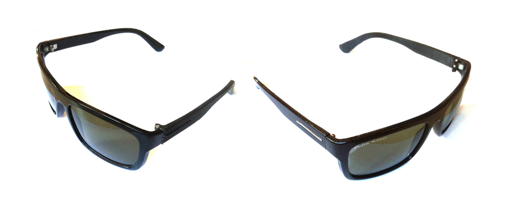
Step 2: Include the USB Key

To my point of view, there are 2 main methods to modify the arms and add some objects inside. I'll explain each one, the first one in this step to add the USB key, the other one in the next step to add the pen.
METHOD 1: The goal is to recreate the object you want to use (here an USB drive), then change the shape of the arm according to this object.
- First you have to start after the sub-step 9 explained before.
- Create the object you want to incorporate inside the arm. Make sure it is a bit bigger (I have added 0.25 mm on each side) because we will subtract it to the branch and we need a small offset for the object to fits after.
- Then try to position it in the center of the arm sketch. If it fits perfectly inside with more than 1 mm all around, then you can continue. However if it too big, you will have to redesign the branches. But don't worry it is very easy now.
- Go back to the 2 sketches you made for the arms, and edit them. Project the shape of the object on each side, then add an offset of at least 1 mm. Now redesign the outer shape including this offset.
- Then create the arm just as explained before.
- After having smoothed the edges in Meshmixer (sub-step 30) you will need to do another step if you want to open the arm in Fusion 360 and be able to modify it. You have to reduce the number of meshes: select the full arm (double click on it); in the tab "select", click on "Edit" , then "Reduce"; in "Reduce target", select "Triangle budget", and set "tri count" with a value equal or lower than 10,000 (the higher the value, the more precise the object, but if it is too high, Fusion 360 might refuses to convert it into BRep).
- Then save it as .stl, and open it in Fusion 360. To do so, click on "insert", then "insert mesh" and select the arm in the .stl file.
- As you want to modify the mesh, you have to do the following: In the browser of Fusion 360 (which is most of time situated on the left of the software), right click on the first tab (the name of the object), and select "Do not capture design history", and "continue". Then in "bodies", right click on the arm you just uploaded, and click "Mesh to BRep". Right click again on the first tab of the Browser and click on "Capture design history". Now you can modify the stl!
Note: If the "Mesh to BRep conversion" has been aborted, you have to reduce the number of mesh in Meshmixer as explained before. - Place the object (USB drive) inside the arm using "move", where you want it to fit. Then select both object (arm + USB drive), and click "combine" in "modify". Make sure to select "intersect" in "operation". This way, it creates a hole inside arm with the shape of the USB drive.
- Create an offset plane where you want the arm to open.
- Then select split body in "modify", select the object you want to cut, the plane, and click "ok".
- It is done you just have to print it!
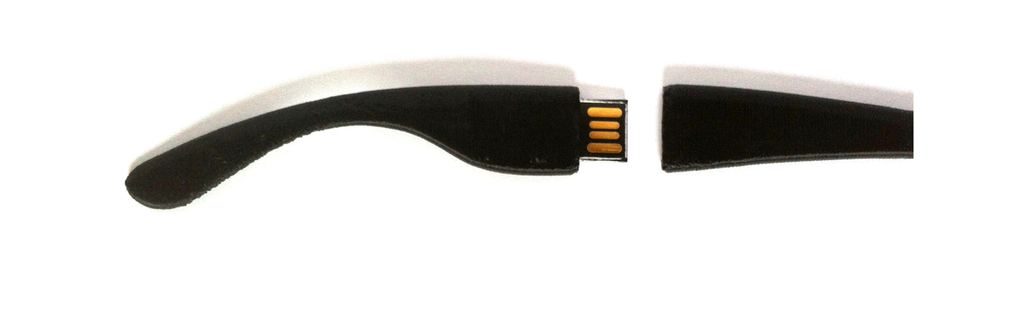
- And here is what it looks like once printed:


Step 3: Include the Pen

METHOD 2: This method uses some planes and the "loft tool".
- Start with the same steps than described previously for the USB drive. Make sure the object will fit inside the arm, or redesign it. Then use Meshmixer to smooth the edges, save it as .stl and import it into Fusion 360.
- Start creating a cut in the arm. I made this cut using the same plane that the one created before for the USB drive. Now the 2 arms have the cut situated at the same place.
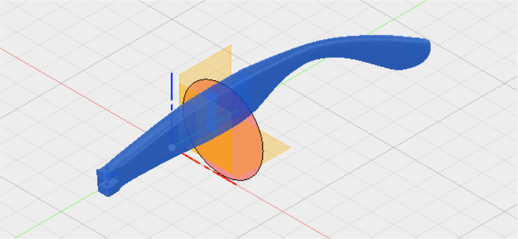
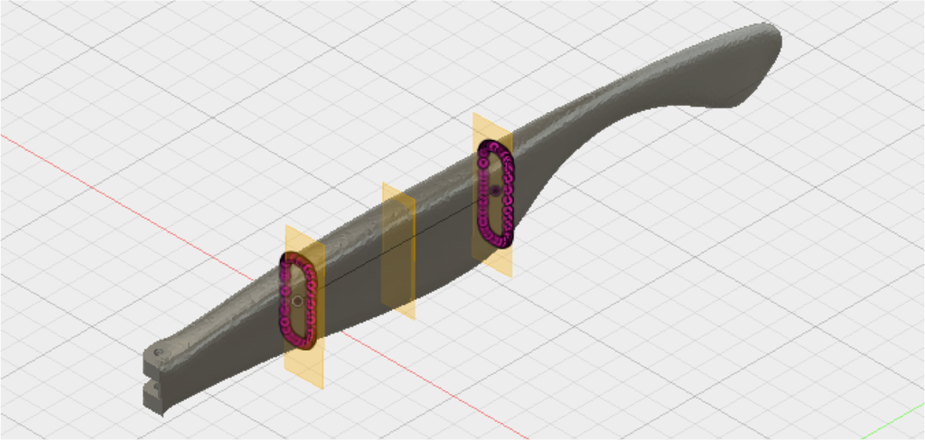
- Create 2 new offset planes. Place them where you want the cartridge to start and finish.
- Create a sketch on each new plane, then in "sketch" go to "project/include" and select "intersect". In "Selection Filter" select "Bodies" and click on the arm. This will project the intersection of the arm, on the new planes.
- Make 2 points centered on the previous sketches.
- Create a plane passing through these 2 points (for example go to "construct", click on "plane through 3 points" then select the 2 points + another random point).
- Make a new sketch on this new plane, and create a line connecting the 2 points. And stop the sketch.
- In "modify", click on "pipe", select the line previously made, and make sure that "cut" is selected in "operation". This will create a pipe where the cartridge will stand.
- Now go back to the middle plan, where the arm is cut. Create a sketch on this plane, and again, draw the intersections of the arm as explained above.
- We are going to create the tip of the pen, so you can hide the proximal part of the arm (the one with the hinge).
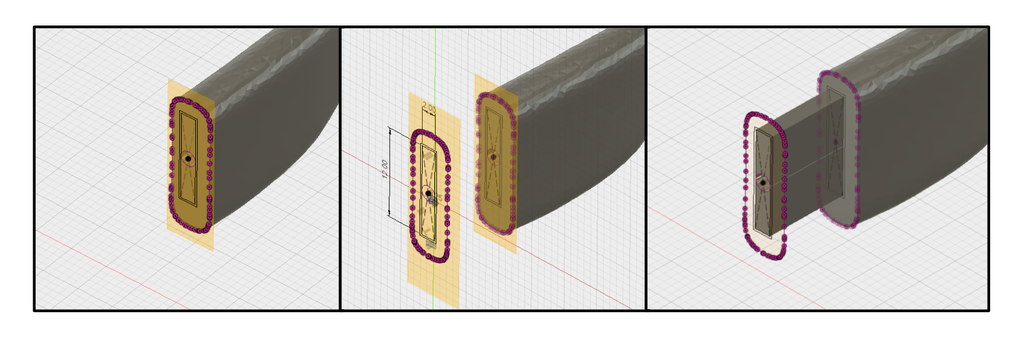
- Create 2 rectangles on the new sketch. One with a minimum width of the diameter size of the cartridge (3 mm in my case) and a length you choose (here 10 or 15 mm for example), and the other rectangle with 0.25 mm offset compared to the 1st one.
- Do the same thing on the other plane as seen on the images bellow.
- Then use the "loft tool" in "create", and select the sketch parts that are facing each other, on the small rectangles only. You will end up with the image bellow. This is the tip of the pen, with a pipe to insert the cartridge.
- Use the "fillet tool" (in "modify") to smooth the edges.
- Then redo all the previous steps, for the proximal part of the arm:
- Hide the distal part you just designed.
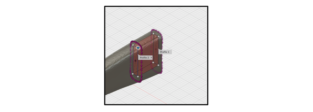
- On the sketches with the rectangles, use the "loft tool" again but selecting the big rectangles, and use "cut". Remember that the tip of the pen is going to be a bit longer. So I have created a pipe that goes 5 mm longer than the plane so the tip can fits perfectly.
- You just have created the second part of the arm that will host the first part containing the pen. So here is what the arm look like: And once printed, and with the cartridge:


 And once printed, and with the cartridge:
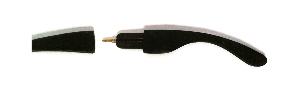
Step 4: Last Tip Before Printing

Finally, as there are thin cavities (to host the USB drive and the cartridge), you might need supports to print the arms. But it won't be that easy to remove them... So to avoid the supports, I have modified the end of the cavities. I have cut the end with a round shape so no supports are needed. You can also create a triangle with 2 angles with more than 45°. And I have printed the objects with the cavities facing down, and with no supports (except for the one hosting the pen, I have used supports, but I made sure they won't affect the pipe for the cartridge).
Also, make sure to have a look on my last article about the best settings for 3D printing, it can be useful!
Step 5: Thank You for Reading


Thank you if you have read the article until the end!
If you want to download the arms I made, you can find them on my thingiverse account!
It was not that easy to explain in detail all the steps, I hope it is clear enough to be reproduced.
I hope you liked this project, feel free to comment I'll be glad to hear if you have some critics (positive or negative) or if you made it!

Second Prize in the
Fix It Contest

First Prize in the
Hiding Places Contest 2017

Participated in the
Lazy Life Challenge

Participated in the
Plastics Contest

Participated in the
Outside Contest 2017


