

Introduction: Cheap Arduino Controlled Light Sockets - Reverse Engineering RF


Smart lightbulbs cost your firstborn child. Which is a shame, because smart lights unlock tremendous potential for home automation, energy savings, and all sorts of cool projects.
If only there was a way to control your lights without breaking the bank...
And now there is! For $19 on Amazon, you can get a 4-lightbulb kit from China that ordinarily is limited to 4 channels from a single remote...but with some creative hacking, can be used to control an unlimited number of channels using an arduino and a very simple RF module!
Here's a video of them in action as part of our smart bathroom project (Instructable for that coming soon!):
Think this is awesome? Don't forget to favorite it and follow us on Facebook!
Time required: 1-2 hours
Total Cost: $19 for four sockets ($5/socket), ~$20 for a transmitter
You should know:
Materials:
- A 4-pack of Vktech Wireless Light Bulb Holders
- Arduino Uno or similar
- 315MHz RF Link Transmitter
Tools:
- IC Clips/hooks
- Bus Pirate (we used the sparkfun version)
- Small Phillips screwdriver
- Computer with a micro USB cable
- A breadboard and spare wire (solid core is best)
Step 1: Reading the EEPROM


We'll start by cracking open one of these light sockets and reading its memory. Grab your screwdriver and remove the two phillips screws holding the housing together. The case should fall open and reveal the PCB inside.
If you look around, you'll see a few capacitors, some diodes, a big box (the relay), a long IC (the microcontroller), a separate board tacked on (the RF receiver), and a little 8-DIP chip marked 24C04 - this is the EEPROM that stores the RF command to turn on the bulb.
Let's take a closer look at what the memory chip holds, shall we? Using the bus pirate and the datasheet for the EEPROM chip, wire up a circuit like the one shown. You should have:
- Bus Pirate VCC -> chip VCC (and to VPU, the pullup pin of the Bus Pirate)
- Bus Pirate GND -> chip GND
- Bus Pirate SDA (MOSI, Orange for Sparkfun BPs) -> chip SDA
- Bus Pirate SCL (CLK, Yellow for Sparkfun BPs) -> chip SCL
- Bus Pirate VPU -> Bus Pirate VCC (the pullup I/O pins are driven from this pin)
Next, let's run a script that will dump the EEPROM data to a file using the I2C circuit we just set up. Using the terminal or command line, navigate to the folder where you downloaded i2c_dump.py and run it as follows:
It'll produce a .hex file showing the hex values of the data.
Open up the .txt file. If it contains nothing but 0x00 or nothing but 0xFF, chances are you need to check your circuit and re-run the dump. If you see a few different values towards the start of the file and a bunch of 0x00's after, you have a successful hex dump!
It's a good idea at this point to try dumping a couple of the other bulbs to see what values change in this code. Don't worry if the hex dumps don't make sense yet, but you should notice that only one specific value in them is changing. Hmmmm...
Step 2: Transmitter Disassembly/Cracking the Code
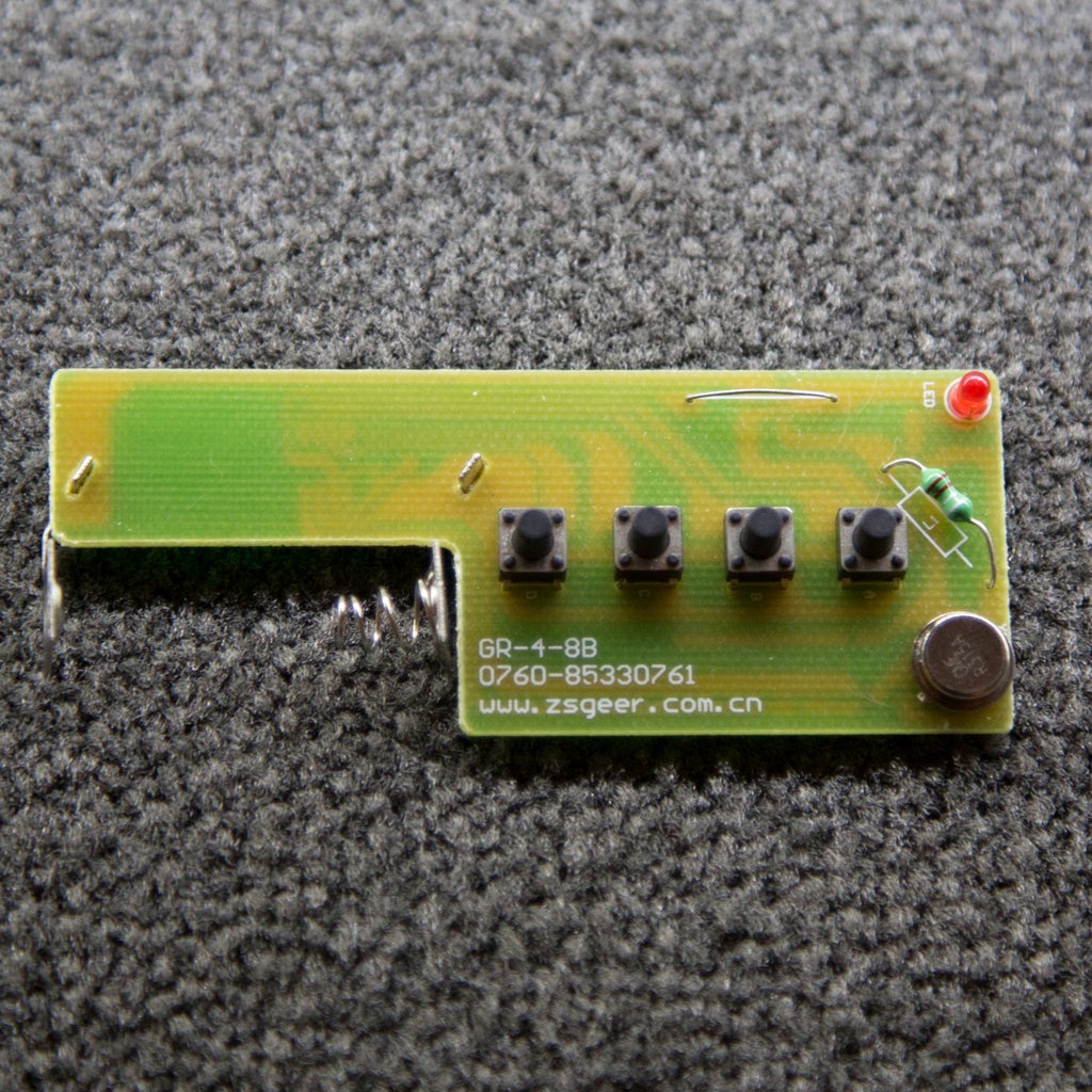

Now it's time to build a circuit that will mimic the incredibly cheap plastic remote. Open up the remote by removing the battery case, battery, and screws. You'll see a couple pushbuttons, some tiny components, a metal crystal package (marked with R315A), and an IC with HS1527 stamped on it. The "315" on the crystal sounds very much like we're operating a 315MHz transmitter, and a quick look at the HS1527 datasheet tells us that we're dealing with an OTP encoder transmitter.
Page 2 is particularly interesting, showing an output format of a 20-bit code and 4 data bits. The code is used to prevent any random device on the same frequency from accidentally turning the lights on, since there's an approximately 1/1,000,000 chance that a random broadcast will match the code. The four data bits correspond to which RF socket is being turned on - this is the last four bits of the hex value that changes between each of the socket's EEPROMs.
So we know the data bits are where the hex data is changing. What about the 20-bit code? Couldn't it be anywhere in the EEPROM? Well, it turns out that programmers are lazy. They really don't want to create extra work and more code, so when reading a serial transmitter broadcast they'd likely want the comparison data arranged in the same way in memory. Looking at one of the dumps, we see something like:
5a5a 0c5a c18c 285a bea3 915a ffff ffff
On another dump, we see:
5a5a 0c5a c18c 285a bea3 925a ffff ffff
And so on. Counting 20 bits to the left of the changing digit (that's 5 hex values), we get the code 0xBEA39. With any luck, we can shove this into a data packet and blast it at the light sockets, and they'll respond by turning on or off!
Let's get to building a new transmitter!
Step 3: Let's Make an Arduino Transmitter!


Wire up your arduino to your 315MHz RF Link Transmitter chip. To do this, you'll want to look at the datasheet and match:
- Arduino GND -> Transmitter GND (pin 1)
- Arduino P7 -> Transmitter Data in (pin 2)
- Arduino 5V -> Transmitter Vcc (pin 3)
Cut a piece of wire approximately 23.8cm long and attach it to the ANT pin (pin 4) on the transmitter. This will be our antenna.
Now grab our Arduino files (original author: salanki) and change the value of "char *address" in hs1527_rf_light.ino to the 20-bit address you found in the previous step. Upload this to your board. The default code will toggle each of the four lights in sequence.
If all of this works, you now have four individually addressable wireless light sockets!
Step 4: Optional: Simultaneous Toggling
Our use case was in the bathroom - we had a set of four overhead lights that we wanted to turn on and off all at the same time. But with the current transmitter code, you can clearly see when each light turns on. How do we fix this?
Modify the EEPROM, of course! We'll just make the activation data bits the same for each of the transmitters.
Crack open each of the RF sockets, and do the following for each:
- Attach the bus pirate (same way as before)
- Type "[ 0xA0 0x00 ]" in the bus pirate terminal (This sets the read pointer to 0x00)
- Run "[ 0xA1 r:16 ]" which will print the first 16 bytes. Note the 0x91/2/4/8 value is at position 0x0A (i.e. the byte #10 counting up from zero)
- Write a new hex value by running "[ 0xA0 0x0A 0x91 ]". This writes the value 0x91 to position 0x0A.
When you finish with all the sockets, each one should be keyed to button 1 on the transmitter. If you re-run the test program again, you'll find that all the lights turn on with only one code!
Similarly, we can use the bus pirate to change the 20-bit code, letting us turn on more than four lights at a time with a single code. Try it and see what happens!
Step 5: That's All, Folks!
With your new RF-hacking powers, you can now build smart, computer-controllable lightbulbs for a mere $5 a pop!
If you like this Instructable, don't forget to favorite it and follow us on Facebook
References:
The RF light sockets: http://www.amazon.com/Vktech-Wireless-Remote-Contr...
The HC1527 chip datasheet: http://sc-tech.cn/en/hs1527.pdf
EEPROM found in the bulb sockets: http://www.atmel.com/Images/doc0180.pdf
Bus pirate pinouts (Scroll to bottom for Sparkfun pins): http://dangerousprototypes.com/docs/Common_Bus_Pir...
BusPirate Scripting in python: http://dangerousprototypes.com/docs/Bus_Pirate_Scr...
i2c_dump.py script for dumping EEPROM: https://gist.github.com/kost/592e96381ca3c97abe21
Viewing a hex dump in vim: http://vim.wikia.com/wiki/Hex_dump
The vpullup problem: http://dangerousprototypes.com/docs/Practical_guid...
HS1527 encoder original INO files: http://forum.arduino.cc/index.php/topic,99714.0.ht...
315MHz transmitter datasheet: http://dlnmh9ip6v2uc.cloudfront.net/datasheets/Wir...

Finalist in the
Formlabs Contest

Participated in the
MAKE ENERGY: A US-Mexico Innovation Challenge

Participated in the
Make it Glow!


