

Introduction: 5x5 LED Cube (Arduino Uno)

This is a step by step explanation of how to build a 5x5 LED cube using an arduino. I did this project for my undergraduate electronics class and it took me about 2 weeks to complete.
Note: Apparently, some of the links for the supplies and code aren't working, if you need them send me an email at amh02010@mymail.pomona.edu.
You can find a video of the working LED cube on youtube here:
http://www.youtube.com/watch?v=KiE-WHqU5a8&feature=youtu.be
And here's another:
http://www.youtube.com/watch?v=6zRlhSzXP80&feature=youtu.be
Step 1: Supplies
I used www.mouser.com and www.amazon.com to order my materials for this project. The main parts needed are:
-125 LEDs
-30x 150 Ohm resistors
-5x 3-8 Line Decoders
-5 NPN Transistors
The manufacturer numbers and prices can be found in the attached document though the cost was about $40.
Additional required materials:
-Arduino uno
-Soldering iron
-Solder
-Sturdy wire (for structure of cube)
-Insulated wires
-Breadboard
-sockets (for decoders)
Attachments

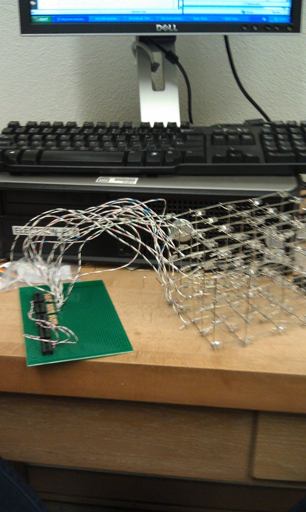
Step 2: Cube Construction


Unfortunately, I have not perfected the construction of the cube. I found this portion of the project both frustrating and painful (hot wires!).
I began by assembling the 5 layers or planes of the cube. This involved connecting all the cathodes of the LEDs together. Id did this by poking 25 LEDs (about 1 inch apart) into a piece of styrofoam. I bent all the anodes out of the way and soldered the LEDs in 5 columns and then two rows on the end (see picture). Be careful when soldering because the entire wire becomes hot and I accidently burned myself multiple times by touching the end of one of the wires.
The next step in cube construction is even trickier. You need to connect the anodes of the LEDs in 25 vertical columns without letting any of them (or their connecting wire) touch the cathode planes. The way I did this was leaving the top plane in the styrofoam and placing ~6 inch wires next to the anodes. I used needlenose pliers to curl the anodes into loops so that it was easier to solder. Alternate the directionality of the wires of the cathode planes for stability. See photos.
Step 3: Wiring and Breadboard

See attached pdf for a circuit diagram. 3-8 decoders labeled A-E. But a brief overview...
1) Solder sockets into board (w/o decoders in)
2) Wire in series with socket pins according to 3-8 decoders as follows (see http://www.alldatasheet.com/datasheet-pdf/pdf/15570/PHILIPS/74HC238N.html? for data sheet for further information)
Note: Error in circuit diagram. Z0 should actually be connected to the VCC wire.
"A"-"C" 3-8 decoders
-connect A0 together and to digital output 4 on arduino
-connect A1 together and to digital output 3 on arduino
-connect A2 together and to digital output 2 on arduino
-connect g to ground on arduino
-connect Vcc to 5V on arduino
-connect Y0-Y7 of "A" to COL1-COL8 (with 150 ohm resistor between)
-connect Y0-Y7 of "B" to COL9-COL16 (with 150 ohm resistor between)
-connect Y0-Y7 of "C" to COL17-COL24 (with 150 ohm resistor between)
"D" 3-8 decoder
-connect A0 to other AO and to digital output 4 on arduino
-connect A1 to other A1 and to digital output 3 on arduino
-connect A2 to other A2 and to digital output 2 on arduino
-connect g to ground on arduino
-connect Vcc to 5V on arduino
-connect Y0 to COL25 (with 150 ohm resistor between)
"E" 3-8 decoder
-connect A0 to digital output 6 on arduino
-connect A1 to digital output 5 on arduino
-connect A2 to ground on arduino
-connect g to ground on arduino
-connect Vcc to 5V on arduino
-connect Y0 to E3 of "A" decoder
-connect Y1 to E3 of "B" decoder
-connect Y2 to E3 of "C" decoder
-connect Y3 to E3 of "D" decoder
-connect pEN (E3) to digital output 12 on arduino
3) Solder 5 150 ohm resistors into board. Then solder base of 5 transistors in series with resistor. Ground the collectors. Solder wire leads to emitters of transistors to Z0-Z5 (planes of cube).
Attachments

Step 4: Programming
CLARIFICATION:
The column numbering can be seen in the attached pdf. The first column is the back left corner, then the numbering increases left to right for each row.
With respect to the programming, the data sheet I attached on the previous step will be helpful (ESPECIALLY THE LOGIC TABLE). You code the arduinio to ouput a 5-digit binary number to the decoders and then to the 25 columns (via digital ouptuts 2-6, where setting a pin to high is a one and setting a pin to low is a 0). Then you also code the arduino to set a specific plane of the cube to high to determine which plane of a specific column you want to light up. To light up multiple LEDs from the same decoder you have to flash between the "columns" at a delay rate less than the human eye can detect. Please see my attached code to find out how to light up individual LEDs, columns, planes, spell letters, and create patterns.
Attached is a sketch showing the labeling of LEDs, columns, and planes.
Note: My method of coding is very long because I don't remember much from my intro to computer science course. Could shorten code by using if statements, loops, etc.
EX.
To illuminate LED28 (in COL3, plane 2)
You want all the levels low, besides the second one so,
digitalWrite(Z0, LOW);
digitalWrite(Z1, HIGH);
digitalWrite(Z2, LOW);
digitalWrite(Z3, LOW);
digitalWrite(Z4, LOW);
And then to call the correct column, look at the logic table in the datasheet., Begin by setting p3 and p4 to determine which decoder connected to the cube to direct to. Because we want COL3, we want the first decoder "A" which means setting
A0, A1, A2 to LOW (So Y0 goes high and enables the first decoder). A2 is always low on the initial decoder "E" so set its other address inputs to low as well such that...
digitalWrite(p3, LOW);
digitalWrite(p4, LOW);
Then need to determine which output of decoder "A" you want. Since it's the third column you want the third output. When A0, A1, A2 are LHL, Y2 goes high so,
digitalWrite(p0, LOW);
digitalWrite(p1, HIGH);
digitalWrite(p2, LOW);
Attachments

Participated in the
Make It Real Challenge


