

Introduction: 6-Wheeled R/C Wheelbarrow With Pneumatic Dump


This project started out life going to be an r/c lawnmower. It has now morphed into this six wheeled creation.
Step 1: UPDATE! PLEASE SEE VIDEO BELOW. THANK YOU.
Step 2: Robot: Materials & Tools
Materials: Electric wheelchair (from EBay, Craig's List, Pawn Shop, or steal your grandmother's), motor speed controller (from on-line vender like www.robotmarketplace.com, R/C radio transmitter, r/c receiver, mini high torque servo, (from on-line or local hobby shop). Tools: Assorted wrench set, assorted screwdriver set (flat & Phillips head), Allen wrench set (SAE & Metric), wire cutters, wire strippers. Optional: Battery power screwdriver, electric tape, 14AWG wire (if necessary to extend wheelchair battery leads). (NOTE: these instructions are contingence on the make and model of your wheelchair).
Step 3: Robot: Build

First, disconnect batteries. Next, carefully unplug & remove the controller from the wheelchair. Next, make sure to remove all wires. (Note: ONLY cut what is necessary, this controller can be sold on line to help fund the project). Next, remove the seat; it should just slide off the seat pole along with the seat adjustment mechanism. Next, (If applicable) unbolt and remove the housing covering the frame & batteries. You should be down to just the wheel chair frame. Next, there should be 2 12 volt batteries with the wiring harness attached. (NOTE: Before making any connections or cutting any wires disconnect the battery wires). Next, use the existing wiring harness to make the wiring connections to the motor speed controller and the wheelchair. (NOTE: wire the controller according to the manufactures instructions). Next, before making the wiring connect to the r/c receiver, consult the manufactures instructions on the binding process for the r/c radio transmitter and the receiver. Next, after you have bound the r/c transmitter and receiver attach the wiring connection from the receiver to the speed controller. Next, if the receiver came with a plug type end on the input wiring. This plug will have to be cut off and the wires stripped in order to connect them to the controller. (NOTE: wire the controller according to the manufactures instructions). Next, reconnect your battery wires, turn on the r/c transmitter, and then begin the setup & testing of your new wheelchair robot.
Step 4: Wheel Barrow: Material & Tools

Materials: 2 wheeled wheelbarrow (Any wheelbarrow will work, but the wheelbarrow used was a True Temper wheelbarrow from Home Depot. The True Temper wheelbarrow has square stock metal handles which make it very easy to work with). 2- 3 inch sticks of all thread, 1- 6 inch stick of 1x2 inch steel tubing, 1- 6 inch stick of 1x3 inch steel tubing, 3- sticks of 1x1/4 inch flatbar steel, 1- 3 inch stick of 11/2x11/2 inch steel angle, 1- 6 inch stick of 1 inch black iron pipe, 1- 6 inch stick of x1 1/2inch black iron pipe, 1- 1/2 x18 inch stick of black iron pipe, 2 & 3 inch x 3/8 inch bolts with nuts and washers. Tools: Band saw, 4 inch grinder (with grinder disks and cutoff wheels), welder (preferably Mig welder), wrench set, screw driver set, battery operated drill/screwdriver, drill press, drill bits, driver bits, gloves, safety glasses, welding jacket, welding hood, wire cutters, socket set, tape measure, scribe, pencil, sharpie, straight edge, automatic center punch.
Step 5: Wheelbarrow Build


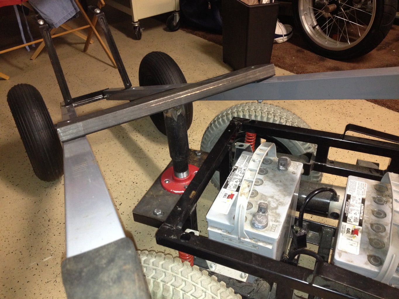
First, remove the barrow from the handles and set the barrow aside. Next, measure, cut and drill the cross member that will support the handles, barrow and kingpin. Next, cut and drill steel plate to attach the pipe floor flange to. Next drill the wheel chair frame and bolt the steel plate and the pipe floor flange to the frame. Next, measure and cut pipe for kingpin. Next, screw pipe into floor flange check height with wheelbarrow frame. Next, install the wheelbarrow section of pip over the wheelchair section of pipe. Next, make any necessary adjustments and tack weld the wheelbarrow section of piping to the cross member.
Step 6: Pneumatic Lift Assembly: Material & Tools
Material: 1- pneumatic cylinder, and the same cash of materials from the wheelbarrow steps. Tools: Use the same cash of tools as in the wheel barrow steps.
Step 7: Pneumatic Lift Assembly: Build


First, measure cylinder closed and at full stroke. Next, measure the opening between wheelbarrow handles and below cross support member. Next, lay out cut and drill locations on the material. Next, cut and drill the material. Next, assemble the modified material as shown. Next, check fit and test movement. Next, fit and tack weld the lift mechanism reinforcements material in place as shown. Next, check fit and test movement. Next, check the fit of the pneumatic lift assembly in the wheelbarrow frame. Make sure that the lift assembly is centered and level. Next, on the wheelbarrow frame, locate and drill the frame to receive the front pivot point of the lift assembly. Next, slide the all thread through the frame and lift assembly and bolt in place. Next, cut off the excess all thread. Next, support lift assembly and level. Next, Measure, cut and drill steel angle to attach to the lower section of wheelbarrow frame. Next, bolt the angle steel in place. Next, measure, cut and tack weld the front rests for the lift assembly. Next, measure, cut, drill and bolt on the front barrow hinge support. Next, measure, cut and tack weld the front barrow hinge. Next, measure, cut, tack weld the front frame hinge bracket. Next, measure, cut and drill the inner pin for the front hinge. Next, check the fit-up and movement. Next, remove barrow. Measure, cut, drill and bolt on the steel rear barrow support. Next, reinstall the barrow and hinge pin. Next, measure, cut, check fit-up, install and tack weld the rear barrow pivot arms to the rear barrow support. Next, Check movement and make any necessary changes.
Step 8: Air System: Material & Tools
Materials: 1- pneumatic cylinder, 1- 24 oz. CO2 tank, 1- paintball gun regulator, 2- flex fill hoses with tank valve, 1- 10 inch long braided steel paintball hose, 1- three-way air toggle switch, 2- 90 ells, 1- 3/8 inch to 1/4 inch reducer fitting, Teflon tape (all the preceding items can be acquired from your local paintball shop),Velcro, coat hanger, mini high torque servo (local hobby shop). Tools: Needle nose pliers, wrench set, small flat head screwdriver 3/16 inch Allen wrench. (NOTE: use Teflon tape on all threaded fittings except the tank valve).
Step 9: Air System: Build


First, get paintball tank filled. Next, remove the tank valve from one of the flex hoses. Next, attach the remaining flex hose to the tank using the tank valve. Next, attach the other end of the flex hose to the inlet port of the regulator (NOTE: see manufactures instructions for proper installation instructions). Next, Attach braided steel hose from outlet of regulator to inlet port of toggle switch valve (NOTE: see manufactures instructions for proper installation instructions). Next, connect remaining flex hose from outlet port of the toggle switch valve to the push port of the pneumatic cylinder valve (NOTE: see manufactures instructions for proper installation instructions). Next, set up the system (regulator) using the instructions provided by the manufacture (Be Very Careful Here!). Next, These components will be installed on the frame of the wheel barrow as shown about using Velcro except for the toggle switch valve and the servo, they must be screwed to the board (NOTE: your configuration may be slightly different). Next, cut the long length of the coat hanger, measure, bend and install to connect the servo and toggle switch valve as shown. Next, connect wiring to battery and test the servo, r/c connection & toggle switch valve movement. (NOTE: perform this test with the CO2 OFF!).
Step 10: Controls Mount: Material & Tools
Materials: 1- 24x24x1/2 inch piece of plywood, 2- 2 1/2 inch self tapping screws. Tools: circular saw, sharpie, battery operated screw driver, Driver bit.
Step 11: Controls Mount: Build


First, lay the plywood on the wheelbarrow handles. Next, mark the inside and outside of the handles with the sharpie. Next, use the circular saw the cut the outside lines only as shown. Next, lay the plywood on the handles and screw in the self tapping screws. Next, remove the screws and turn the plywood over. Next, install the air system as outlined in the Air System steps. Next screw the board to the handles.

First Prize in the
Remote Control Contest


