

Introduction: 8-Bit Arduino Valentine's Heart


Show your 8-bit love this Valentine's day by printing and wiring up your own "8-bit Heart".
I picked my resistors using this resistor calc:
I then divided the result by three for a few reasons: Firstly the LEDs I'm using (like my dearest) are cheap and dim. Secondly each LED will only be briefly lit for less than 1/3 of the time, and finally (like my love) nothing lasts forever.
BOM:
- 1 Arduino, any basic (eg not LeoStick)
- 17 Red LEDs (or 34)
- 17 Resistors (~50ohm in my case)
- 1 Ribbon Cable
- 2 Printed 8 bit hearts
- 2 M3 x 30mm bolts with nuts (and optional washers).
- 1 Set of header pins (18 pins total)
- Heat shrink
Step 1: Print the Heart


First we will need to decide on which setup we'll be doing. The options are for a single heart, two or four. In this example I'll be doing the single (If you really loved them you'd do 2 or 4, but I'm like "meh, good enough"), but it's simple enough to extrapolate the 2 and 4 heart versions by multiplying the led count by 2 or 4 and adjusting the resistors (actually I suspect wiring all four may require more power than the Arduino can supply, but I'll update when I know for sure).
Edit: Woops... I seem to have forgotten the STL and thingiverse links (bonus .scad for the real 3d geeks).
http://www.thingiverse.com/thing:246633


Step 2: Glue LEDs

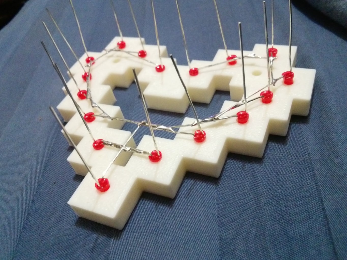
I actually did this step after soldering the grounds as I thought I might be able to get away without using glue... how wrong I was. Save yourself hours of fiddling and hassle and just glue the LEDs in right off the bat. Before gluing bend all the ground leads to 90deg as flat as you can, this will form our grounding web in the next step. As you glue the LEDs in now try to align all the ground legs with each other and all leading down to the bottom LED.
Step 3: Solder It All Together
This one is a bit of a three parter... if you know what your doing you may have your own ordering/methods, but these are mine:
Part A - Solder "ground web"
=====================================
Now we can solder all the negative legs of the LEDs together... this looked good enough half of me wanted to just stop here (see picture). Attach one of the ribbon cable wire to the ground web somewhere near the middle.
Part B - Solder ribbon cable heart end
=====================================
Now add a bit of heat shrink and solder each of the LEDs to the ribbon cable. You can now attach the back (or joiners for QuadHeart... coming soon) plate of the 8 bit heart using two M3 screws (or PLA spikes for the adventurous).
Part C - Solder resistors/headers
=====================================
For my heart I soldered the resistors directly to the header pins and covered them up with heat shrink before soldering to the ribbon cable... more heat shrink and Bobs-your-uncle.
Step 4: Bolt on the Back (and Side) Plate(s)
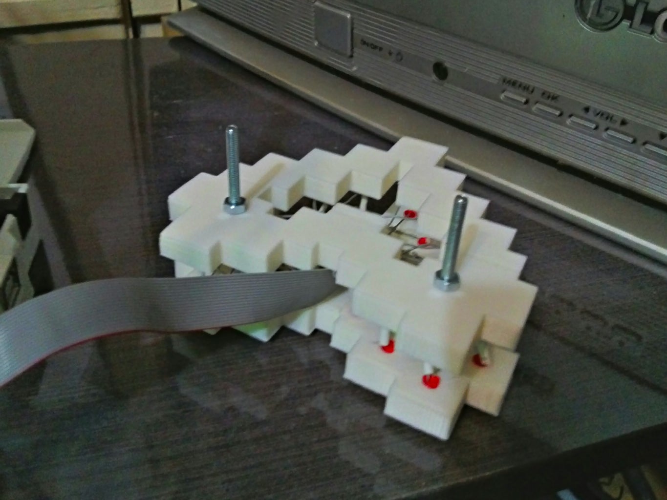
This one is a bit self explanatory, but there are plenty of alternative options.
Initially I had planned to mount it over a window (hence no lower bolt), but found that two bolted back to back about 2cm apart was quite stable.
Gluing together four would be even more stable, and I'm working on a connector block so this setup won't need glue.
Alternatively the bolt holes could be used to mount a single heart to a mounting board or other project.
Step 5: Plug It All in and Load Firmware


Now your eight bit heart should be now ready to plug in and load up firmware. The attached sketch just pulses the heart up and down. If you have copied my design and are writing your own sketch keep in mind that I have selected resistors with lower ohm than the LEDs can handle over a long period of time. So if you leave any LED on for an extended period of time there is a good chance you'll blow it. Simple rule of thumb: keep it moving and keep less than 1/3 lit and you _should_ be ok (at least that's my understanding, correct me if I'm wrong).
8 Bit Heart Arduino Sketch:
// 8 Bit Heart Beat
// A sketch to run on the 8 Bit Heart with custom madas timing
// and customizable LED array for easy reordering, like I needed.
// By: PuZZleDucK
// Licence: GPL3
// Date: 28/01/2014
int arraySize = 17; // Number of LEDs in your heart... more means you love me.
int ledArray[17] = {4,3,2,A0,A1,A2,A3,A4,A5,12,11,10,9,8,7,6,5}; // Note the 'european' style of starting at 4.
volatile long time = 0; // Madman timing...
void setup() { // Just set all our pins to output
for(int i = 0; i < arraySize; i++) {
pinMode(ledArray[i], OUTPUT);
}
}
void loop() {
time++; // Advance time index
if(time == 2147483647L) {
time == 0; //The end, near the beginning.
}
// Using modula arithmatic to light up oposing LEDs
digitalWrite(ledArray[arraySize-((time-1)%arraySize)-1], HIGH);
digitalWrite(ledArray[time%arraySize], HIGH);
delay(50); // You may think 100 might be more romantic, but I found 50 to be a nice balance between boring and seizure inducing.
digitalWrite(ledArray[arraySize-((time-1)%arraySize)-1], LOW);
digitalWrite(ledArray[time%arraySize], LOW);
}//loop
// I used this for debugging... I pray you will never need it.
// but if you do it's great like this: blinkN(time%arraySize, time%arraySize+1); //this will blink each pin in turn with its own order number.
void blinkN(int pin, int count) {
for(int i = 0; i < count; i++) {
digitalWrite(pin, HIGH);
delay(100); // You may think 50 would be quicker... but I can't count that fast :p
digitalWrite(pin, LOW);
delay(100);
}
}//blinkN
Attachments

Participated in the
Valentine's Day Contest


