

Introduction: 8x8 LED Matrix


This instructable will show you how to make a 8x8 LED matrix in witch you can control evry single LED and create your own patterns as long as they only need 64 pixels to show them in one color.
Update 25.09.10
I've added a pattern generator to create patterns but not all of it's features are complete
Attachments

Step 1: Materials
Materials you need:
-8x8LED matris (can make one but i bought mine)
-16x120Ohm resistors
-8xNPN transistors (I used C547B)
-1xPIC16f690
-prototype board (or you can make pcb for this)
-wire
-5V power supply (you can use a voltige regulator but I just power mine from a usb port)
Tools:
-PIC programmers (all the pic programmers from microchip exept for pickit1 will work)
-Software- MPLAB (free software from microchip)
-Soldering iron
-A vacum pump for removing solder is good to have
-wire cutters
Skills you need:
-soldering skill (being capable of making good solder connections within 5-10 sec.)
-Logic thinking to some level
If this is your first experiense using microcontrollers I recommend that you start with a more simple project.
Step 2: The Circuit


This is the circuit schematic.
NOTE that you will need to look at the datasheet of your led matrix (if you bought one) or know how to connect the matrix you made
Step 3: The Code.
The code is written in assembly.
This code is based on the code from https://www.instructables.com/id/3x3x3-LED-Cube/ but you can not use the genorator that he supplys sense it only has 27 diodes and is has "layer1 layer2 layer3" insted of "line1...." and also has only got 3x8 bit numbers while have 8x8 bit numbers
NOTE the letters in this code may display in reverse sense I accidentally reversed the ground in my display.
Attachments
Step 4: Editing Patterns Displayed.
You can add and remove patterns as you like in this matrix.
to add a pattern simply generate the pattern with the generator that is included in this step....
It is a .rar file so use winrar to unzip it.
And yet agin I want to thank portreathbeach for having the source code of the genorator in his document about the www.instructables.com/id/3x3x3-LED-Cube/
to make a moving design you can few steps to the subroutine and it will be like this.
;-----------------------------------------------------------------------------------------------;
; Test sub routine ;
;-----------------------------------------------------------------------------------------------;
Test:
movlw b'01111100'
movwf Line1
movlw b'11000110'
movwf Line2
movlw b'00000011'
movwf Line3
movlw b'00000011'
movwf Line4
movlw b'00000011'
movwf Line5
movlw b'00000011'
movwf Line6
movlw b'11000110'
movwf Line7
movlw b'01111100'
movwf Line8
movlw b'11111111'
movwf Layer4
call Output
movlw b'01111100'
movwf Line1
movlw b'11000110'
movwf Line2
movlw b'00000011'
movwf Line3
movlw b'00000011'
movwf Line4
movlw b'00000011'
movwf Line5
movlw b'00000011'
movwf Line6
movlw b'11000110'
movwf Line7
movlw b'01111100'
movwf Line8
movlw b'11111111'
movwf Layer4
call Output
return
you will also have to add a function at the bottom of the asm file
The bottom few lines will be somthing like this.(the call function is to call the subroutines you can call them in any order you want to)
Loop:
call Someroutine
call Test
call Test
goto Loop
end
Attachments
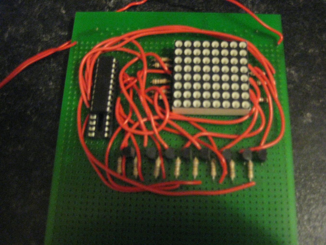
Step 5: The Finished Product


Here are the results of the matrix... you can control evry single LED on this matrix through the code
Participated in the
Get the LED Out! Contest


