

Introduction: A Practical Guide to FDM 3D Printing Gears


This past Christmas season I put my printer to good use making unique presents for my family. Everyone with a workshop or a garage got a custom geared light switch cover.
Designing this toy definitely took a few tries to get the desired effect. While doing so I researched and collected notes on perfecting printed gears and I thought it was interesting enough to share. This Instructable is intended as a general guide for designing & printing FDM 3D printed plastic gears.
The geared light switch cover is a neat example of something you should be able to design on your own after reading this instructable.
For those of you who have a 3D printer: you can find the STL files attached to this step for free!
- (Please note the 'personal use only' licence for this design, this means- No Sharing, selling, or remixing to share/sell. Please don't use my files to compete with me.)
- (The assembled device measures 6.25" in diameter. The largest printed part is 5.875" diameter)
For those without a 3D Printer: I am selling finished Geared Light Switch Covers on my blog here.

Step 1: Printing & Assembly Instructions for Geared Light Switch


Print all parts minimum 3 perimeters all sides top & bottom, with 15% infill. I recommend 0.3mm layer thickness maximum. Any material will work as long as you can prevent warping, which would devastate this device.
The wrench file is the only one that needs print supports/scaffolding.
Assembly Instructions: (Read in full before starting)
1. Clean up the gear teeth with a razor blade so they will mesh smoothly then place them on the plate in the same rotational orientation they were when you printed them. (The pin on the sun gear is to the right and the handle of the ring gear is top and center.)
2. Pin the planet gears in place by pressing the nuts into the holes.
3. Apply a smidge of clear drying glue (glue stick works well) to the business end of the wrench then install it from the side so it snaps on the nut. The glue is to keep the wrench attached to the nut. The wrench also holds the sun gear down onto the assembly.
4. Soften the clips using a heat gun for ~10 seconds. Just enough so they can be opened up. Then align the bump on the clip with the hole on the back of the plate and press over the ring gear. (The holes on the back of the plate may need cleaned up with a knife to aid this, depending on how good your printer is). Then squeeze the clip as it cools. This will ensure that everything is securely held together.
Step 2: FDM Printing Specific Benefits & Examples of Gear Use:


So why choose to 3D print gears over alternative gear making methods and what strengths does 3D printing offer?
Printed plastic gears are a cheap, quick, and customizable motion transfer solution compared to alternative ways to make gears. Complexity & 3D variations are essentially free. The prototyping & creation process is quick & clean. Best of all, 3D Printers are common enough that a set of STL files can be shared with tons of people eager to use them online.
Of course printing gears using the commonly available plastics is a sacrifice in surface finish and durability compared to injection molded or machined plastic parts. But when designed correctly, printed gears can provide efficient and reasonably high load transfer and are an ideal solution for some applications.
The majority of functional applications take the form of a speed reducer, usually for a small electric motor or hand crank. This is because electric motors do high speeds really well, but they arent naturally good at producing low speed/high torque very well without being geared down. Examples of this done well include:
- The ubiquitous 3D printer extruder gear drive.
- This Nema 17 Stepper Motor Planetary Gear Reducer
- This High Load Linear Actuator
- This 3 Jaw Lathe Chuck.
Step 3: FDM Printing Specific Challenges:


1. Printed gears usually require a little post processing prior to use. Expect to have to bore holes to the right size & clean up teeth with a blade.
Center hole shrinkage is a very common issue that occurs even on expensive printers. This is the result of multiple factors. Some to thermal contraction of cooling plastic and some is because the holes are modeled as polygons that have lots of segments cutting short around the perimeter of the hole. (Always export gear STLs with high segment counts.)
Slicing software can also have an effect as different programs may choose different spots for the hole to actually start. If you consider the absolute innermost edge of the extruded plastic to be the inside edges of the hole and shoot to make that the desired hole size, then the hole diameter is easy to stretch out of tolerance by a tiny bit when you press something inside. So a slicer designer may choose to intentionally make holes tighter.
Also, any misalignment between layers and any discrepancy between the actual and intended extrusion width can have a measurable hole tightening effect. To combat this I usually oversize holes in the model by ~.005” across the diameter. For similar reasons and to make sure gears have enough space to function when printed next to each other, I recommend leaving a .4mm clearance between meshing gear teeth in your model. This creates a bit of backlash but will prevent printed gears from locking together in use.
2. Another common challenge is getting a solid infill can be difficult on small gear features. Gaps inside tiny teeth are common even when the slicer is set to 100% infill.
Some software is better than others at automatically fixing this, but one way to manually solve is to increase the layer overlap. RichRap did a great job documenting the problem and various solutions on his 3d printing blog.
3. Standard FDM 3D printing challenges: Thin walled parts are weak, overhanging parts need breakaway scaffolding, part strength is significantly weaker in the Z-axis. All the same, my recommended print settings for gears are no different than for anything else 3d printed. Based on testing I did a while back I recommend that you use the rectilinear infill with a minimum of 3 perimeters. I would recommend as fine of a layer height as you have the ability & patience to print, so as to create smoother teeth.
4. But then again, plastic is cheap and your time isn't. If the application is critical or just cumbersome to replace a broken gear on then you may as well print the gear mostly solid to avoid the chance of any non-wear related failure. The most common failure modes of printed gears are:
*Tooth wear until slipping. (A long term failure mode, see Step 10 on lubrication.)
*Tooth breakage. (If overloaded.)
*Connection to shaft failure. (See Step 7 on attaching to shafts)
*Hub or spoke breakage. (This is a rare failure mode that only occurs if the gear was printed poorly, with not enough infill, or was designed with too thin of support spokes.)
Step 4: Why Involute Is Important:


It’s really common to see gears improperly designed by the hobbyist community online because doing it the right way is hard. Tempting as it may be, poorly designed gears don’t mesh properly and suffer from excessive friction, stress, backlash, and jerky uneven rotational velocity.
See the first image attached to this step. The difference is subtle to the untrained eye, but doing it the right way will be more accurate and have better properties in the end.
Involute (spur) gear teeth are called such because the contour of gear teeth has a special curve inward. This is done in such a way that ensures the rotational speed and angle of contact of the gears stays constant throughout their rotation. A well designed set of gears should transfer motion almost exclusively through a rolling action, with very little sliding involved.
Modelling involute gear teeth from scratch is really tedious so before taking the time to do it, first check if you can get by with one of the gear design templates I link to at a later step.
Step 5: Tooth Design Tips: Optimum Number of Teeth


Think about this: If you wanted a 2:1 gear ratio for that linear actuator pictured earlier, how many teeth would you put on each gear? Are you better off with 30 & 60 teeth, 15 & 30, or 8 & 16?
Each of those ratios would have the same mechanical advantage but each would produce a very different set of gears if printed.
More teeth per gear increases the contact ratio (average number of teeth in contact at any time) and provides smoother rotary motion. But adding more teeth requires that each tooth get smaller to fit on the same diameter of gear. Tiny teeth are weaker and more difficult to print accurately.
Alternatively, reducing the number of teeth on a gear gives you more space to have large strong teeth.
3D printing a tiny gear is like trying to use a thick sharpie to color inside the lines of an itty bitty coloring book. (This is 100% a function of nozzle diameter and X-Y resolution of the printer. The Z-resolution has nothing to do with minimum feature size.)
If you want to test your printer’s ability to print tiny teeth, try the free 3d printable bevel gear model test attached to this step. My printer makes it all the way to the top but the teeth start looking untrustworthy around 1/2" diameter.
The trick is to keep the gear teeth as large as you can get away with, without crossing the low-tooth-count threshold or introducing undercut.
One more thing to consider before picking the tooth count: Prime numbers & factorization.
The 15 and 30 tooth gear pair are both divisible by 15 so the same teeth will meet up over and over again causing concentrated wear points.
A better solution is to make the pair have 15 & 31 teeth. (This is the answer to the question asked at the beginning of the step).
While this doesn’t produce exactly the same ratio, it will provide a consistent wear on the gear set. Grime and imperfections in the teeth will spread across the whole gear rather and distribute the wear.
Also, it’s a good rule of thumb to keep the tooth ratio between be between ~0.2 and ~5. If you need even more mechanical advantage it may be better to add an additional gear into the system, else you end up with a monstrosity.
How few teeth is too few?
This is information that can be looked up in resources like the Machinery Handbook. 13 is the minimum recommended for gears with a 20 deg pressure angle, and 9 is the minimum recommended for gears with a 25 deg pressure angle.
Fewer teeth that that are not recommended because it would require undercut, which weakens the teeth and is tougher to 3D print without having meshing problems.
Attachments

Step 6: Tooth Design Tips: Pressure Angle & Making Strong Teeth


Pressure angle? What’s that best one?
This is the angle between the normal of the tooth face and the pitch diameter. Teeth with larger pressure angles (more triangular) are stronger but are also less efficient at transferring torque. They are also easier to print, but in use they create larger radial loads on the supporting shafts, are more noisy and prone to backlash and slippage.
For 3D printing a 25 deg angle is a good balance of chunkiness and efficient motion transfer on a palm sized gear.
How Else Can I Make Teeth Stronger?
Simply making the gear thicker will obviously strengthen the teeth as well. Doubling the width of the gear essentially doubles its strength. A good general rule is for the thickness to be at least three to five times the circular pitch of the gear.
The strength of gear teeth can be approximated by considering each tooth as a small cantilever beam. When viewed this way you can see that adding a solid wall over a face to reduce their unsupported area greatly increases the strength of gear teeth. Depending on the application, this technician can also be used to help reduce finger pinch points.
Step 7: Shaft Mounting Methods:


Press Fit on Knurled Shaft: The easiest method to do but is not seen very often. Watch out for plastic creep which will reduce the torque capacity over time. This also cannot be disassembled without destroying the gears usability.
Set Screw on Shaft with Flat: A setscrew is drive through the gear to contact a flat spot machined on the shaft. The set screw is usually threaded into the plastic gear directly or through a nut that is trapped inside the gear via a square hole. Each method has its own risks.
Directly threading into the plastic runs the risk of stripping the delicate plastic threads. The nut trapping method solves this problem but if not done properly the hub breaks when you apply enough force to secure the shaft with the set screw. Make the hub Beefy!
Adding specialized heat-insertable threaded inserts as seen here is also a great way to improve the shaft gripping strength.
Recessed Hex- a hexagonal well which traps a hexagonal nut or the head of a hex-head bolt. Make sure to print lots of solid layers around the hex so that a mounted bolt cant strip through the plastic. I've successfully used set screws to secure nuts in place to prevent spinout at high torques.
Key & Keyway- Not often seen in the hobby 3d printing world.
Integrated Shaft: This design is highly susseptible to torsional failure of the shaft. This is very difficult to do properly with fdm printed gears since you have to print gears oriented normal to the print bed, any shaft integrated with the gear will end up having its weak Z-printed axis subjected to high loads.
Step 8: Optimal Materials for Plastic Gears:
What is the best material? My short answer for the hobbyist 3D printing community from the perspective of finished gear quality:
Nylon > PLA > ABS > PETG
Nylon filament is an incredibly strong, durable, and versatile 3D printing material. It’s low friction coefficient, high inter-layer adhesion, and high melting temperature make it an excellent choice for 3D printed gears. The drawbacks of nylon are its propensity to absorb water and the difficulty of printing with it.
That leaves most folks with the choice between ABS & PLA. PLA has high rigidity and superior wear properties over ABS which make it a better choice when application temperatures allow.
PLA’s low heat distortion temperature makes ABS a better choice for applications involving temperatures above ~75C (ABS softens around 105C).
By the way, the biodegradability of PLA is an overhyped property. Yes, PLA is biodegradable. But not in a scale that is in any way noticeable for the end user. Do not equate biodegradability with water solubility. To biodegrade this plastic, you need a specialized composting facility with a controlled environment.
PETG is a ductile material but it is also softer, more flexible, and less scratch resistant than either ABS or PLA which makes it a worse choice for gears. (PETG material data sources here and here.)
Also of note, recently people have been experimenting with annealing PLA for the purpose of increasing stiffness, strength, and heat deflection, at the cost of some slight part shrinkage (possibly non-uniformly). More on annealing PLA gears here.
Step 9: Special Tips by Gear Type:

Helical & Herringbones (double helical): Usually seen on printer extruders, these are annoying to use, but have their merits. They are useful for their ability to increase contact ratio, self-center, and self-retain. (Self-retaining is the annoying property because it makes installation more work.) This type of gear also can't be easily manufactured with conventional machining equipment like a gear hobbing machine. 3D printing is by far the easiest way to make them.
Worm & Worm gear: These can be difficult to 3D model so its very tempting to use a ger template for these. My tip here is that the gear ratio between the worm gear and worm is the number of teeth on the gear divided by the number of flutes in the worm. (Count flutes by looking at the end of the worm and see how many spirals start. Most have 1 to 3 spirals.)
Rack & Pinion: Converts rotary motion into linear motion & vice versa. Rather than rotations, the gear ratio determines the linear distance traveled by the rack with each rotation of the pinion. The tip here is that you can calculate the gear teeth per inch (tpi) of a rack all you do is multiple PI times the pitch diameter of the mating pinion gear. (Alternatively multiplying number of pinion teeth times circular pitch produces the same result.)
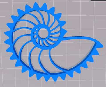
Non-circular gears like the nautilus gears shown in the images, have few practical uses outside of novelties.
Step 10: Lubrication of FDM Printed Gears:
You can get away with operating plastic gears without lubrication in light-load low-speed low-frequency applications. But if you have a high stress environment you can try to increase the working life by lubricating the gears to reduce friction and wear. In any case, all gears function more effectively with lubrication and will have a longer service life
For things like 3d printer extruder gears I recommend heavy grease. White lithium, PTFE, or silicone based are all great stuff for this. Apply the lube by wiping lightly with a clean paper towel or dust-free cloth applicator, and spread evenly by rotating gears multiple times.
Anything is better than no lube, but be sure to choose a lubricant that is chemically compatible with the plastic material. And never forget, WD-40 sucks as a lubricant. Though it makes a decent cleaner.
Step 11: Tools for Making Your Own Gears:
You can create great quality custom gears using only free software. I mean sure, paid programs exist for creating truly optimized perfect gear meshes and tweaking very fine parameters to optimize performance.
But if you are using FDM 3d printed gears anyway, then good enough is good enough. Just be sure to design all your gears using the same tool to ensure that they mesh as intended. Gears are best designed in pairs.
.
Option 1: Find existing gear models & modify or rescale them to suit your needs. Here is a list of databases to find models of off the shelf gears.
- McMaster Carr: wide array of 3d models, go-to for hardware
- GrabCAD: Huge database of user submitted models
- 3DContentCentral: Database of user submitted models
- Misumi: 3d models of small mechanical parts
- Stock Drive Products: 3d models of many different kinds of gears
.
Option 2: Designing gears ‘from scratch’ using free online gear generating templates:
If you can’t get the right details you need by copying an existing model, the next best option is to use an involute gear generator template to make your own custom gear. Fortunately there are many cool tools out there to help.
*I created a collection of useful gear models that can be customized on Thingiverse here:
*Matthias Wandel's classic gear generator program here.
*Online STL File Creator, simple & direct, here.
*GearGenerator.com Generate Spur Gear SVG Files: (That file can be converted to an importable DXF file type here. Though some software, like Blender, can import SVG files directly without any tricks/conversions.)
*https://inkscape.org/en/ Is a free program for vector drawing and it has integrated gear generator. Decent tutorials on using inkscape for gears here and here too.
.
STL File Editors:
The output of most gear template generators is an STL file, which can be annoying if you need to make features that aren’t in the generator. STL files are like the PDF file of the 3d world, they are notoriously difficult to edit but it can be done!
TinkerCAD: I LOVE this silly browser based CAD because it is quick and easy, and one of the rare 3d modellers out there capable of modifying STL files. www.Tinkercad.com
MeshMixer: Good program for stretching out organic shapes. http://meshmixer.com/
.
Design from Scratch: If you're feeling brave then I'd recommend reading the classic gear reference manual, Dudley’s Handbook of Practical Gear Design. That in addition to the attached Excel based gear calculator, if for nothing else just to double check the strength of the teeth.
Attachments
Step 12: Non-FDM 3D Printing Tips
Most people, even devoted hobbiests, do not have direct access to other 3D printing technologies for making gears. Though there are services out there that can do this for you,.
SLA - Great for professional gear prototyping. The printing layers are invisible and this process can made very detailed tiny parts. On the other hand parts are expensive and can be somewhat brittle. If you use this process to prototype what would be an injection molded gear then forget about coring out the part. Make it solid or it will break in use!
SLS- Very accurate process that produces strong parts and doesn't require supports for overhanging structures. It can make complicated/detailed builds and is good for thin wall parts (< ¼”). Printing layers are almost invisible too... BUT, the gritty finish (due to the nature of powder based printing) is highly wear prone. Heavy lube is required and even still I don't recommend SLS gears for long term applications.
BinderJet- Good for detailed/precise multi-colored decorative or non-structural parts. Good for making crazy colors but the parts are very brittle and gritty, so not good for functional gears.
...
Well that's all the 3d printing gear design notes I've got for now. I hope this guide helps some makers out there.
If you liked this then please take a second to vote this this instructable in the 3D Printing Contest, the Homemade Gift Contest, and the Epilog Laser Contest!
(I'm salivating just thinking about the possibilities of a new laser cutter, muhuhaha! I'd love to get my hands on one to learn and share an instructable with awesome laser cutting tips! Funny thing, this instructable was inspired by a lasercut wood geared lightswitch cover. Just google the words 'planetary geared lightswitch'. )
More of my writings & projects shared here: https://engineerdog.com/
PS: Do you have any more resources or gear templates to add to the list? Let me know in the comments!

Fourth Prize in the
Design Now: 3D Design Contest 2016

Participated in the
Epilog Contest 8

Participated in the
Homemade Gifts Contest 2016


