

Introduction: A Simple Time Delay Circuit


I finally decided to add another line to my charge controller and I wanted a steady power output instead the PWM that comes off of the dump controller so I made this handy little circuit to take a PWM signal and change it to a constant DC signal.
Step 1: Gather the Materials
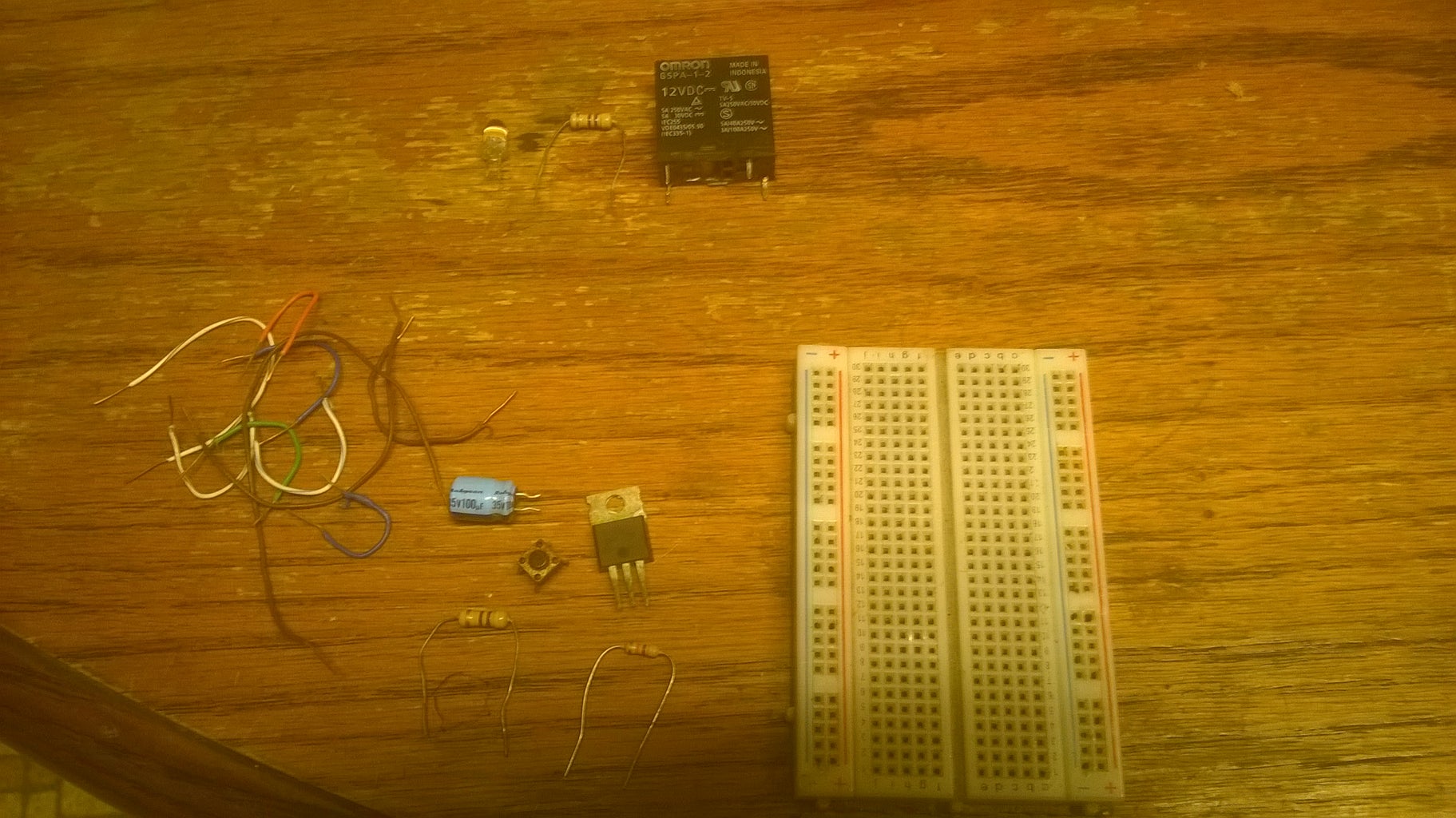
To build the basic circuit you will need:
- A MOSFET. I used an IRF3205
- A capacitor
- Two resistors
- Jumper wires
Step 2: Assemble the Circuit

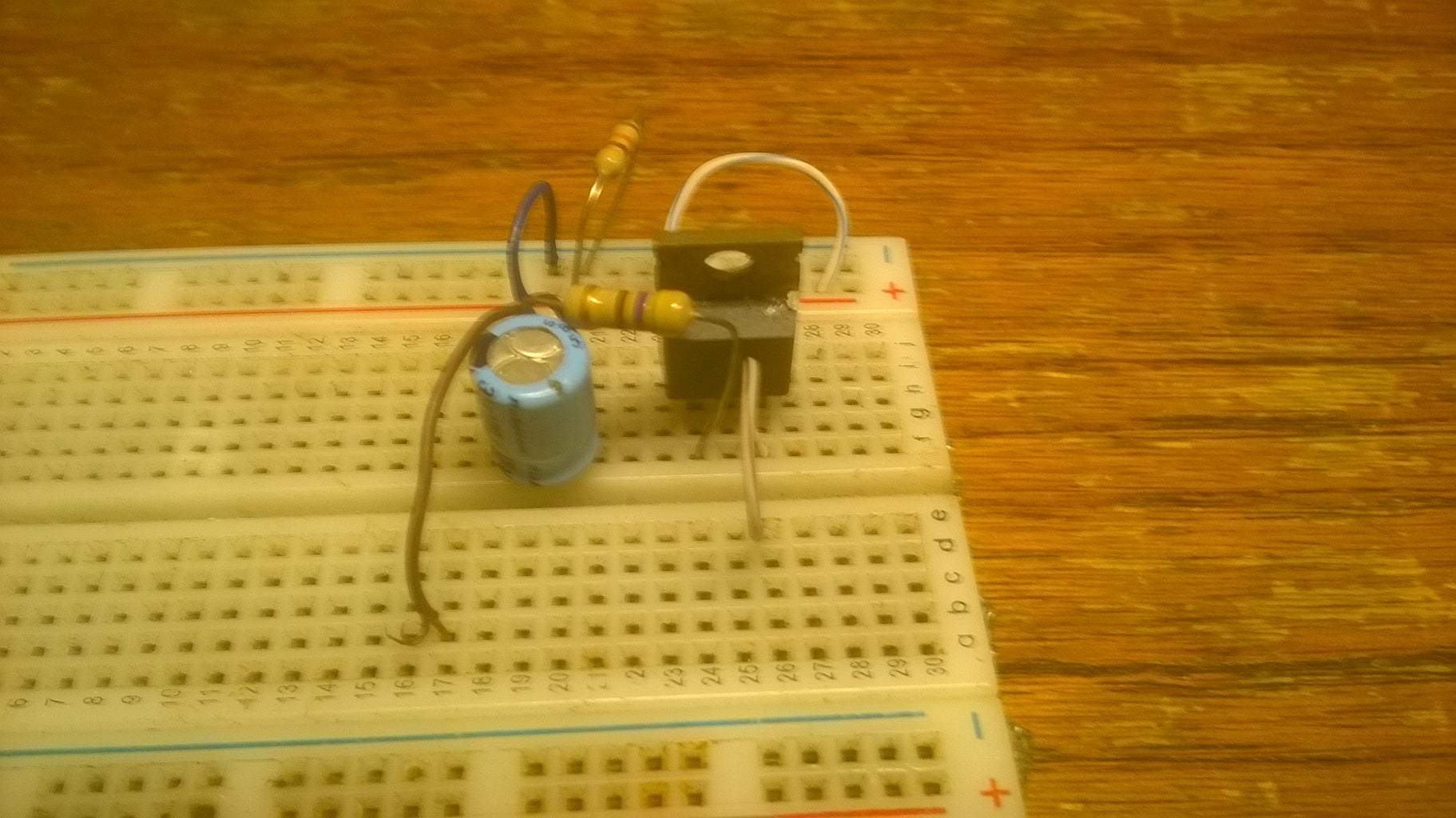
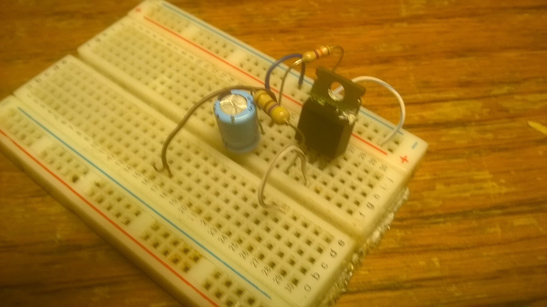
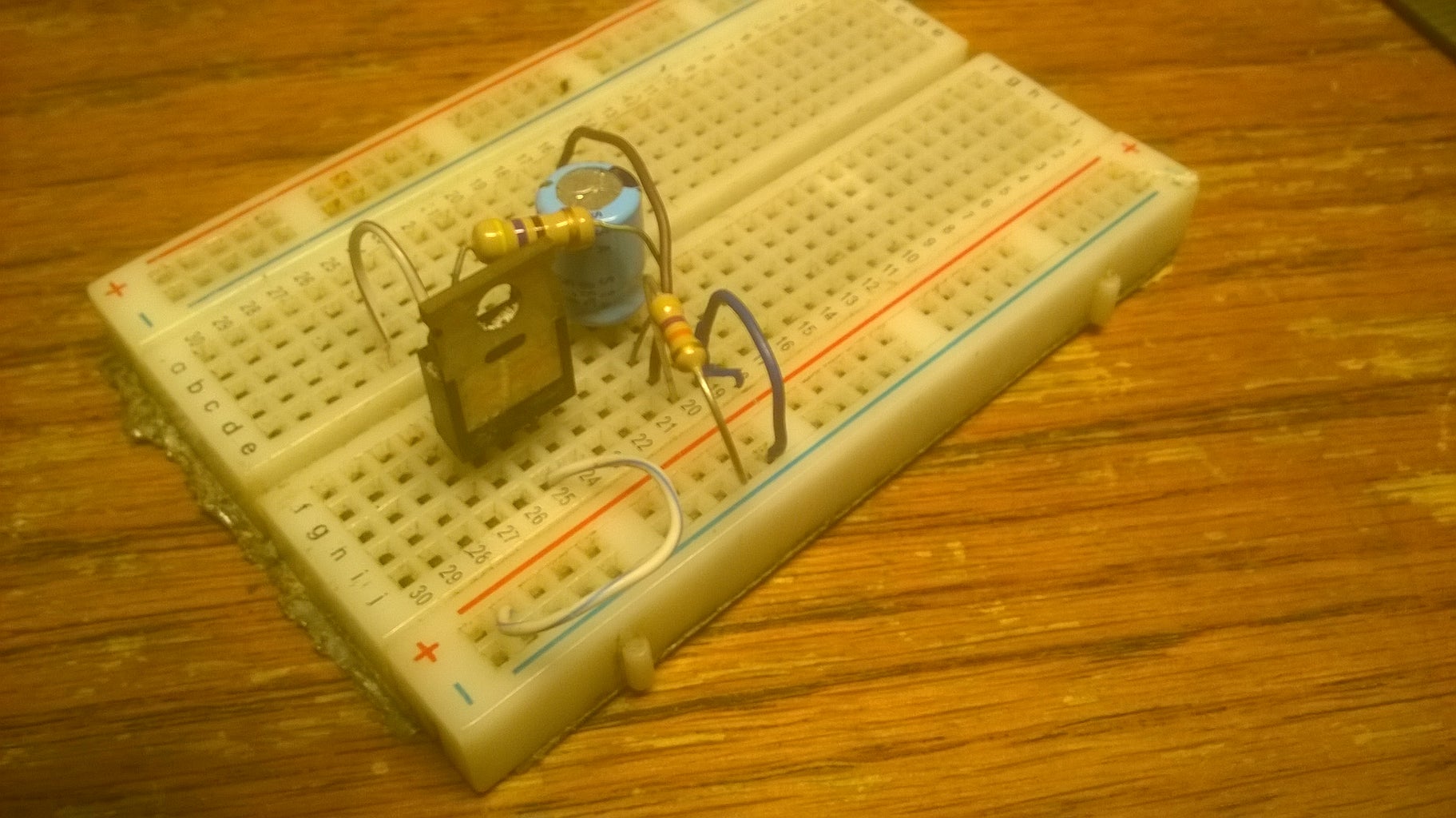
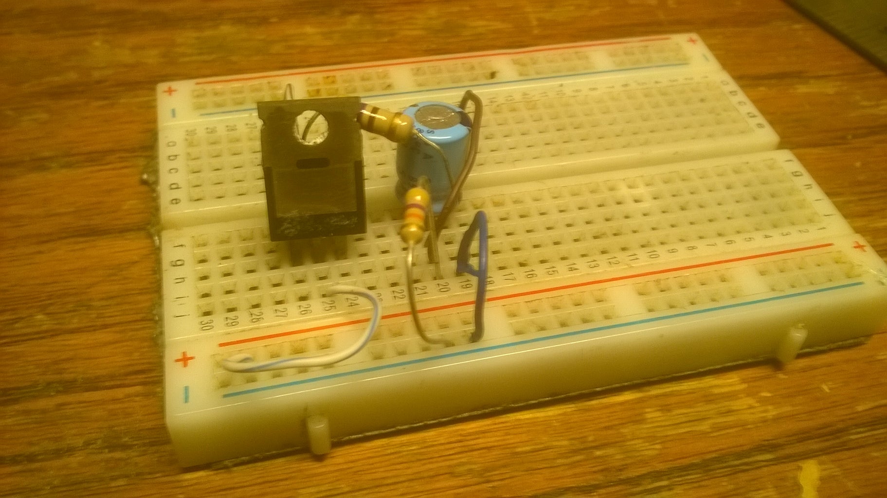
Assemble the circuit according to the schematic.
Step 3: Testing and Tuning
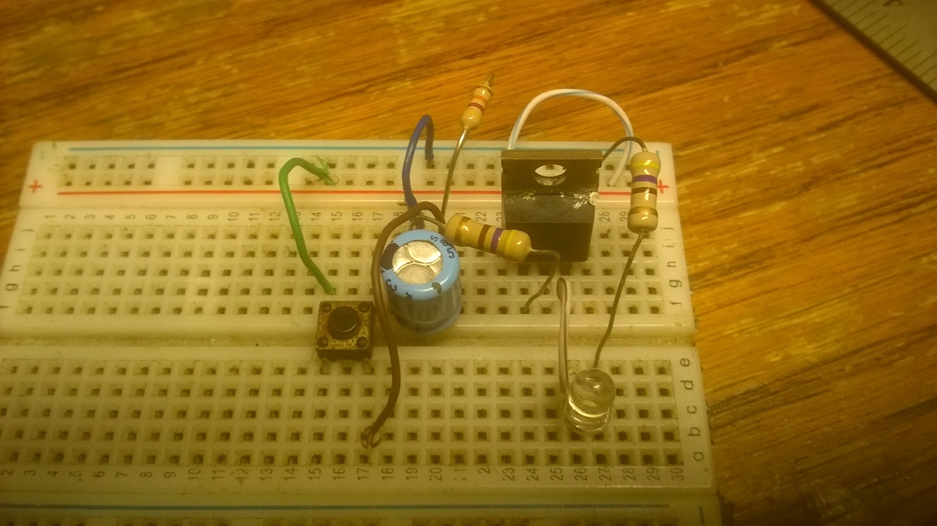
Its now time to test the circuit and add the extras.
Add a button connecting the positive rail to the signal in line and connect an LED and a resistor to the signal out line. Apply power and push the button, if it lights up for a short time then fades out, the circuit is working properly and you can now add the relay if you do so choose. The way this circuit works is when the signal in, line goes high and charges up the capacitor and turns on the transistor. The resistor connected to ground slowly drains the capacitor of it's charge and when the capacitor reaches a certain voltage, the transistor fades out and shuts off. What the relay does is act as a type of quasi schmitt trigger and provides a nice transition from on to off without fading by breaking the contacts when the output from the transistor hits a certain voltage. This action would be handy for running electronic devices that can't really tolerate the in between voltages very well such as an induction motor driven pump (AC) or an inverter (DC).
Like what you see here? Consider supporting me on Patreon.


