

Introduction: A Simple and Very Easy Inverted Pendulum Balancing Robot


Let's make a simple inverted balancing robot, and operate it.
You need only half a day to do them, if you have an arduino and some materials.
[a video of a robot you would make]
introduction:
After a few work with arduino, I have thought of making an inverted pendulum. Then I had two policies for the project.
- simple as possible
- bootstrap (without referring to website)
Though they has been kept (*1), it has demanded more than whole a week to make my robot balance itself. So simplicity of my robot seems to be held in its body, circuit and program (called "sketch"). It has only an analog gyro-module (at $4 (*2)), two plane motors (at $1.5) and two analog ICs (at $1.5) to drive these motors.
(*1) I have referred websites for two matters; a formula for inverted pendulum and a troubleshooting the gyro-module I used.
(*2) 100 JPY = 1 USD I use as exchange rate.
A solderless breadboard in a picture above would show its simplicity. And a video thereunder shows it works well enough.
One who has made a LED blink with arduino ever could assemble her/his inverted robot in half a day or less according to my recipe below. But I think it is similar to solving a puzzle to make it balance on its wheels. Thus I show a solution in three steps not to spoil a puzzle. I wish videos and pictures could cover my poor English.
* A Japanese version of this instructable is available also.
** Additional information, Aug. 20 2014:
A simpler alternative program, ver2.0, has been available in Step 5.
*** Another version has been published later, in which a digital output gyro sensor produced by STMicroelectronics is used instead of two analog output sensors. It is easier to get the digital gyro outside Japan. And the fine soldering in Step 2 is not required for the digital gyro.
Step 1: Gather Materials

Body (using TAMIYA's Educational Construction Series)
- a Universal Plate Set (2pcs.)
- a Universal Arm Set
- a Double Gearbox (Left/Right Independent 4-Speed, two DC motors included)
- a Slim Tire Set (36mm, 55mm Dia.)
Electrics
- an arduino UNO
- a small solderless breadboard
- some jumper wires
- two motor driver ICs (TOSHIBA TA7291P)
- a gyro-module (Akizuki-denshi K-04912: sensor ENC-03R on this module)
- four AA batteries
- a 4AA battery holder
- a 9V battery (PP3)
- two battery snaps
- some rubber bands
[tutorial for Step 1]
[commentary 1]
I have felt that analog gyro-module listed above has individual difference. So I think it better to purchase two or three modules together. And as showing in Step 11, an additional module could make robot work more stably.
[commentary 2]
If it is hard to get the gyro-module listed above, similar one with the same analog sensor (ENC-03R) might be substituted. For example a module sold online would be available. (Its price is near 4 times to Akizuki's one.) Though it seems to have op amp, the factor scale to amplify I cannot find.
Step 2: Solder Wires to Some Components


First you should solder wires to some electrical components.
- solder wire to each point of 2 motors (4 points in all)
- cut 4 jumper wires in half (8 half jumpers gotten)
- solder these half jumpers to 8 wires of 2 motors and 2 battery snaps
- cover each point soldered with chip of tape for insulation
- solder header pins to an Akizuki's gyro-module
- solder a fine wire to either point of a capacitor "C6" on this module
[tutorial for Step 2]
[note 1]
An Akizuki's gyro-module listed above has 2 analog gyro-sensors on its surface. Either sensor is "ENC-03R" made by Murata-seisakusyo. Only one of them is used for inverted robot. This sensor outputs 0.67mV per unit angular velocity (1deg/sec) and it is amplified to ten times with a op amp on the reverse face of the module. (Vo at pin 1 of this module is 6.7mV/dig/sec.)
But this module picks up not only angular velocity but also angular acceleration by its filter (HPF). Capacitor C6 on this module is a main element of HPF. To avoid picking up the latter, soldering a wire to this capacitor is done.
Step 3: Assemble a Body of Robot

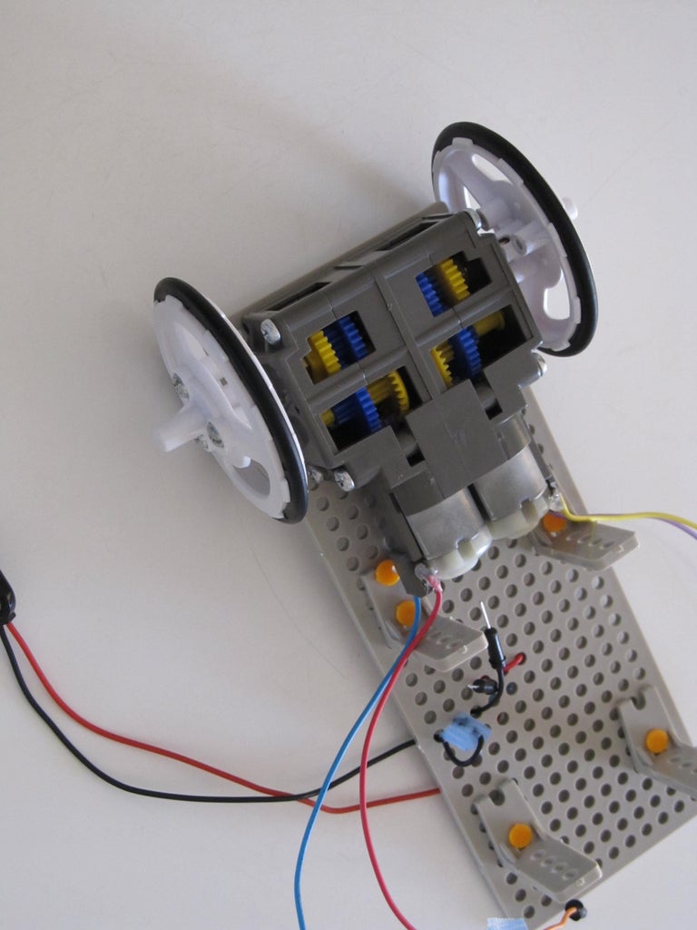
To build a body of inverted robot, TAMIYA's Educational Construction Series are used.
- make two V-shaped cuts to a Universal Plate
- attach 4 L-angles included Universal Arm Set to this Plate
- assemble Double Gearbox to make its gear ratio 114.7:1
- mount 2 motors with 4 wires to this Gearbox
- attach this Gearbox to Universal Plate above
- assemble Slim Tire Set (two 55mm Dia. wheels gotten)
- attach these wheels to shafts of Gearbox above
[tutorial for Step 3]
Step 4: Put Electrical Components Together


Put electrical components together and attach them to the body built in the former step. Then a robot without program is gotten.
- referring to a picture of breadboard above, plug a gyro-module and two motor driver ICs at your breadboard
- wind some rubber bands around the breadboard and attach it on the lower L-angles of body of robot
- according to a wiring diagram above, plug jumper wires at the breadboard
- and plug either wire of the battery snap which would be connected to a 4AA battery holder
- wind a small rubber band around arduino and attach it on the upper L-angles of body of robot
- according to a wiring diagram above, plug jumper wires at arduino
- insert four AA batteries to 4AA battery holder
- wind a bigger rubber band around the body of robot and fix the battery holder to the back side of robot
[tutorial for Step 4]
[note 2]
The robot gotten here has no power switch. To turn on (off) power, battery snap is connected (disconnected).
Step 5: Upload a Sample Sketch to Arduino


Using IDE a sample Sketch for inverted robot is uploaded to arduino.
- if you cannot find MsTimer2 library in IDE, install it from website(*)
(* Another simpler sketch, ver2.0, has been available since Aug. 2014. It does not need MsTimer2.)
- connect arduino to PC via a USB cable
- disconnect the battery snap from 4AA battery holder
- lay down robot on desktop or floor and leave at rest
- download(*) a pdf file attached at the last line in this step (* you get a corrupted program if you open this file in web browser and copy its contents)
- open the file in proper reader and copy the whole of text in the file
- paste the copy to IDE and correct misprints
- upload corrected sketch to arduino using IDE
[note 3]
To make an inverted pendulum balance itself, motor torque is controlled dynamically. This control method is expressed as a plane formula with 4 variables related to the state of pendulum.
"motor torque = k1 * angle of pendulum
+ k2 * angular velocity of pendulum
+ k3 * velocity of the lower end of pendulum
+ k4 * displacement of the lower end of pendulum from a reference point"
k1,k2,k3 and k4 are static coefficients with appropriate values. In a sample sketch in pdf file below, a long equation at line 72 expresses this formula. To make inverted robot balance itself, we have to select proper values for these 4 coefficients respectively and know right value of each of these 4 variables in real time.
A gyro-sensor gives the second variable value, angular velocity of pendulum, dynamically as a voltage at its output pin. And arduino estimates the first variable value, angle of pendulum, contemporaneously by integrating the second variable.
On the other hand, the third or the fourth variable value cannot be measured by gyro-sensor. So another kind of sensor or meter should be used to get them in real time. But our inverted robot has no more device than a gyro-module. Thus it becomes a puzzle to estimate these 2 variables values dynamically. In a sample sketch in pdf file below, 2 masked equations at lines 76 and 77 should be used to estimate them. Here they are left masked not to spoil solving this puzzle.
[note 4]
If some other gyro-module than listed one in Step 1 is used, 2 constants at lines 10 and 11 in the sample sketch in the pdf file would be changed. These constants express k1 and k2 respectively in the formula above. For example if an ENC-03R, gyro-sensor on listed module, is used without op amp, input voltage to arduino becomes 1/10 times. Then the constants at lines 10 and 11 in the sketch should be change to ten times scale respectively.
[a sample sketch (program) for inverted robot]
Copy whole text of "invertedRobot.pdf" or "invertedRobot_v20_noTimer.pdf" below, paste it to IDE and upload it to arduino.
(*1) With some language parameters on the site, an icon of the pdf file is not shown below (at the end of line of this step). Then you should type "https://www.instructables.com/id/A-Simple-and-Very-Easy-Inverted-Pendulum-Balancing/?ALLSTEPS" in address bar of your browser or refer a Japanese version of this Instructable.
(*2) Save the pdf file in your PC and open it in proper pdf-reader. Or you get a corrupted program by opening it in web-browser.
(*3) If "; //72" is not shown at the end of a equation at line 72, substitute whole a equation below for it.
powerScale = ( kAngle * thetaI / 200 ) + ( kOmega * omegaI / 78 ) + ( kSpeed * vE5 / 1000 ) + ( kDistance * xE5 / 1000 ); //72
(*4) Pasting the copy to IDE or editor, misprints such as "/ /" as "//" (an obstacle space inserted) might happen, then correct them.
(*5) An analog gyro-module used here is influenced by temperature. If your robot cannot balance itself well in summer, constant values (45, 85, 57) at lines 10 to 12 in the original sample sketch "invertedRobot.pdf" should be changed such as "52, 95, 53" (added on Aug. 20 2014).
(*6) A simpler alternative sketch "invertedRobot_v20_noTimer.pdf" has been added as ver.2.0 on Aug. 20 2014. Though it does not contain timer library, MsTimer2, for interrupt handling, it could make robot balance better.
(*7) Copyright (C) 2014 ArduinoDeXXX All Rights Reserved.

Step 6: Get an Inverted Following Robot


After a sample sketch uploaded to arduino in the former step, you ought to get an inverted following robot. Though it needs your finger for standing, it follows your finger.
- leave robot still laid for 5 seconds after the upload finished (see picture 1)
- hold the body of your robot and pick it up (see picture 2)
- connect battery snap to battery holder fixed on the back side of robot
- wheels of robot start spinning
- hold both wheels tight and stop spinning (see picture 3)
- set both wheels on desktop or floor and keep static standing to be made center of gravity of robot to be located on its wheel shafts
- after a few second motor torque becomes down and faint noise or chirping "miii" is listened
- then release your hands from robot gently (see picture 4) and put your finger on the top of the body of robot softly
- move your finger forward and backward and see your robot following
- release your finger and see your robot trying to balance but failing
[tutorial for Step 5 and 6]
[note 5]
The signal voltage, which the analog gyro-sensor used here outputs in static state, is not set in advance and is not constant. It depends on conditions and drifts over time. Thus after turning on or resetting arduino, do not touch robot and leave it laid for 5 seconds. During the seconds arduino estimates the signal voltage in static state now.
[note 6]
After the seconds in note 5, as picking up the robot it perceives state changing and spins its wheels. Then the robot has to study proper posture (angle of its body) in well inverted state. This robot is programmed that if it has been in static state for 0.05 seconds it deems itself well inverted.
Hence as picking up the robot and its wheels starting spinning, you should hold both wheels tight and stop spinning. And execute Step 6 since its line 6.
Further if you do not feel changes at line 7 in Step 6, torque down and faint noise of motors, for 10 seconds, arduino might have failed the estimation in note 5. Then you should push reset button on arduino to stop wheels spinning. And after pushing the same button again, execute Step 6 since its line 1.
[troubleshooting 1]
If wheels of robot do not start spinning at line 4 in Step 6, some faulty wiring must be suspected first. Go back Step 4 and verify wiring carefully. Another doubt is a defective gyro-module. Indeed the module I have used first was it.
On the other hand, if your robot does not follow your finger in spite of wheels starting spinning at line 4 in Step 6, four kinds of faulty wiring must be suspected: (1) wires of a motor are set opposite, (2) gyro-module is set reversed, (3) wiring to digital pins of arduino is wrong or (4) analog pin is unplugged. Go back Step 4 and verify wiring carefully.
Step 7: Challenge to Solving a Puzzle
Let's make your "following inversed robot" balance itself without your finger by modifying the sample sketch in Step 5. It might be a puzzle.
- consider why it fails balancing
- get plausible idea and modify the sample sketch
- make your inverted robot try balancing
- if it balances itself you have solved a puzzle and your robot has become an inverted pendulum (congratulation!)
- or else back to line 1 or hesitate to see a solution in Step 8
Step 8: How to Get an Inverted Balancing Robot

Here you see how to get an inverted balancing robot. You need to modify only two lines in the sample sketch in Step 5.
- copy 3 lines below and paste them over lines 76 and 77 in the sample sketch (overwriting them)
vE5 = sumPower; //76a
xE5 = sumSumP / 1000; //77a
// Copyright (C) 2014 ArduinoDeXXX All Rights Reserved.
- execute Step 6 (without a finger support in lines 8 to 10)
- if center of gravity of robot is located on near its wheel shafts, your robot moves back and forward for a few seconds and gets well inverted posture
- see it keeps balancing itself
- if it moves with forward or backward bias, add to or submit from proper integer after "power" at the end of line 74 in the original sample sketch
[tutorial for Step 8]
[troubleshooting 2]
If your robot can not balance itself well in spite of executing Step 6 well, “low battery” in the battery holder on the back of robot should be suspected first. If it is not observed, constant values at lines 10 to 13 in the sample sketch should be changed. I think that line 12 is most critical.
Step 9: Operate Inverted Robot Via Serial Monitor


Now you have an inverted balancing robot. Then let’s control it by serial monitor. You could make it turn right/left and go forward/back.
- update the modified sample program gotten in Step 8 according to the details below
- upload the updated one to arduino using IDE
- after the upload end, start serial monitor from IDE
- select ‘Newline’ and “115200 baud” at bottom right of serial monitor
- leave robot still laid for 5 seconds
- make inverted robot balance itself according to Step 6 (without a finger support in lines 8 to 10)
- input numerical values in upper left window of serial monitor and push the [Enter] key
- see action or change of action of your robot
[tutorial for Step 9]
[note 7]
You can control your robot dynamically by serial monitor from PC via USB cable. For example you input "00" in window of serial monitor and push the [Enter] key, then robot receive ‘0’ and ‘0’ separately. Hence it turns right at a regular angle below twice without stopping.
- a ‘0’ sent makes robot turn right at a regular angle on the spot
- a ‘1’ sent makes robot turn left at a regular angle on the spot
- a number (n) of ‘2’ sent make robot accelerate forward in proportion to the number (n)
- a number (n) of ‘3’ sent make robot accelerate backward in proportion to the number (n)
[an update on the sample sketch (for 4 places)]
(1) Copy the following 5 lines and paste them between lines 17 and 18 in the modified sketch gotten in Step 8.
volatile int drct = 0;
volatile boolean right = false;
volatile boolean left = false;
volatile int fwdBck = 0;
// Copyright (C) 2014 ArduinoDeXXX All Rights Reserved.
(2) Copy the following 26 lines and paste them over line 32 in the modified sketch gotten in Step 8, viz. substitute these lines for “if ( power > 0 ) {”.
if ( Serial.available() ) {
drct = Serial.read();
Serial.println(drct);
}
if( drct == 48 ) { right = true; }
else if ( drct == 49 ) { left = true; }
else if (drct == 50 ) { fwdBck++; drct = 0; }
else if (drct == 51 ) { fwdBck--; drct = 0; }
if ( right == true ) {
analogWrite( 6, 140 );
digitalWrite( 4, HIGH );
digitalWrite( 5, LOW );
analogWrite( 9, 140 );
digitalWrite( 7, LOW );
digitalWrite( 8, HIGH );
delay(40);
} else if ( left == true ) {
analogWrite( 6, 140 );
digitalWrite( 4, LOW );
digitalWrite( 5, HIGH );
analogWrite( 9, 140 );
digitalWrite( 7, HIGH );
digitalWrite( 8, LOW );
delay(40);
} else if ( power > 0 ) {
// Copyright (C) 2014 ArduinoDeXXX All Rights Reserved.
(3) Copy the following 4 lines and paste them between lines 55 and 56 in the modified sketch gotten in Step 8.
drct = 0;
right = false;
left = false;
// Copyright (C) 2014 ArduinoDeXXX All Rights Reserved.
(4) Copy the following 2 lines and paste them over line 74 in the modified sketch gotten in Step 8, viz. substitute these lines for “sumPower = sumPower + power;”.
sumPower = sumPower + power + fwdBck * 4; // 74a
// Copyright (C) 2014 ArduinoDeXXX All Rights Reserved.
Step 10: Unplug the Cable

Substitute a buttery (9V) for USB power (5V) for power supply to arduino. Then arduino is unplugged and your robot stands with no outer wire.
- eject a USB cable from arduino
- connect the second battery snap to a battery (9V)
- attach the battery on the back of robot by rubber band with a battery holder
- plug the positive wire of this snap to Vin pin of arduino
- plug the negative wire of this snap to GND pin of arduino
- your robot starts spinning its wheels if the first snap is connected to battery holder
- make your robot balance itself according to Step 6 (without a finger support in lines 8 to 10)
- see it stands with no outer wire as a completed inverted pendulum
[tutorial for Step 10]
Step 11: Develop Robot Further


Let’s make your inverted robot or your knowledge evolve further. Here three ways are shown briefly. It would be hard to finish the second or the third way within half a day.
(1) Double Sensors
Add another gyro-module on the breadboard of your robot and investigate whether its stability in balancing is improved.
[a record of a robot with double sensors]
(2) Remote Operation with No Wire
In Step 9 your robot is operated via USB cable. Now your robot is unplugged. So let’s operate it with no wire. In terms of simplicity, an infrared module would be the first choice.
[a demonstration of operating robot by a TV remote]
(3) Simulating the Action of an Inverted Robot with Excel
Our inverted robot could be thought constructed from three parts: head, body and wheels. In this simplifying, an equation of motion of the robot can be written with a physics learned at High School. As getting it, the action of robot can be simulated using Excel. The near-proper values of two coefficients in note 3 in Step 5, k1 and k2, could be gotten by this simulation.

Participated in the
Makerlympics Contest

Participated in the
123D Circuits Contest


