

Introduction: A Simple DIY Spectrophotometer


This instructable will explain how to build a fairly basic but working spectrophotometer out of easily sourceable parts.
Of course, this device is nothing compared to a commercial spectrophotometer, but it will allow the builder to understand how such a device works.
Huh? What are you talking about?!
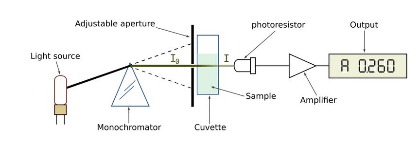
A spectrophotometer measures the amount of light that a certain sample absorbs.
The basic principle:
- A beam of light passes through a prism or diffraction grating.
- Out of the resulting spectrum, a certain (range of) wavelength(s) gets selected by sending the light through a slit.
- The light passes through the sample and hits a detector.
This way, one can build a "spectrometric fingerprint" of a certain sample that will depend on the molecules in the sample.
Cool, let's do it!
I'd once again like to emphasize that this device is certainly not to be compared to a commercial system, but if you're looking for a fun project that will enable you to learn something more about the workings of a spectrophotometer, this project is for you!
Step 1: Sourcing the Parts

You will need:
For the stepper circuit:
- A stepper motor
- an Arduino (or a stepper driver circuit)
- 2x 10k resistor
- 2x 1k resistor
- L293D H-Bridge
- 2x NPN transistor (I used the BC547A)
- A power supply
For the detection and amplification circuit:
- an op-amp (e.g. TL081)
- LDR
- 1x 2k2 resistor
- 1x 4k7 resistor
- 1x LED
General parts
- A base (some kind of board such as a cutting board to mount everything on)
- Cuvette
- Diffraction grating, CD or DVD
- Lightbulb and / or white LED
- Metal or cardboard plaques
- Some connectors
- Some pushbuttons
Step 2: Bring on the Photons!


Light source
First of all, we need a light source. Some possibilities include a small lightbulb or white LED. I installed both, so I could experimentally decide which one was best suited for my purposes.
To construct the light source assembly, find some piece of plastic (or any other material, for that matter) and glue a bulb socket to it.
For the LED, find some kind of connector (I cut off part of and old IDE-connector) and solder some wires to it. Also include a 2k2 resistor in series with the LED to limit the current.
Glue the LED-connector somewhere near the bulb, and put in a LED.
Step 3: Diffraction


Splitting the light
To be able to select a certain wavelength (the color of light depends on its wavelength) we first need to split the light into a spectrum.
This can be accomplished by a diffraction grating. Since most people don't have diffraction gratings lying around the house, a CD can be used as well.
Take a look here for some background information.
Note that a CD does not exactly produce an even spectrum, so it'll give nowhere near as accurate results as with a "real" diffraction grating.
Selecting the wavelength
Since we want to measure the absorbance of the sample at a certain wavelength (or in this case, range of wavelengths) we need to be able to select a certain part of the spectrum.
This can be accomplished with a "slit", i.e. a sheet of cardboard or metal with a narrow slit in it.
To choose which part of the spectrum passes through the slit we can vary the angle with which the light hits the CD.
I chose to use a stepper motor because it can be turned in discrete steps.
Driving the stepper
The stepper motor can easily be driven with an Arduino board. Construct the bipolar stepper driving circuit found here and use the included Arduino-code "spectrostepper.pde", the motor can be controlled by two pushbuttons.
Construct the driver circuit. Then, add pushbuttons by connecting one leg of a 2k2 resistor (pull-down resistor) to ground, connect the other leg to one leg of the pushbutton AND to a digital input on the Arduino.
Then, connect the other leg of the pushbutton to +5V from the Arduino.
Connect the motor itself to a power source, load the sketch in the Arduino and drive the stepper!
If everything went right, the motor should turn 1 step when you push a button; direction depending on which button you press.
Bringing it together
Once you got the stepper going, connect the CD to the motor. (I, once again, used hot glue)
Attachments

Step 4: Selecting the Wavelength


The slit
To accurately select a very small section of the spectrum, one would have to make an extremely narrow slit. Since this is very hard to do at home, I chose to make two slits instead that are not 100% aligned, so only a very narrow band of light can pass through.
Make a small slit in a piece of metal or cardboard. (I used the grinding wheel attachment of my trusty Dremel 4000)
Then, with the light source and CD in place, project a spectrum onto the board and make sure that all parts of the spectrum can be aligned with the slit, depending on the CD's angle.
Now glue the board to the base.
Make a slit in a second piece of material, and align it with the first slit, so that only the narrowest band of light can pass through.
Also it's best to shield the light source from the rest of the device using a piece of metal or cardboard, so that only the diffracted light will hit the slit.
Step 5: Detecting the Light


Amplification circuit
To detect the light that passes through the sample, we're going to use an LDR, or Light-Dependent Resistor.
Though it would be possible to obtain readings by connecting an ohm-meter straight to the LDR, it probably is a better idea to construct a basic amplifier allowing us to use a voltmeter since this will provide bigger differences between slight changes in detected light intensity.
Assemble the amplifier according to the circuit. I used a TL081 opamp. Then measure the voltage between 0V and Output; this will vary depending on the light falling onto the LDR.
Putting the "L"in LDR
Place a cuvette or test tube just behind the slit. Now, glue the LDR in place so that the light passing through the cuvette will hit the LDR.
Step 6: Let's Measure!


Working in the dark
Because the LDR reacts to light, you'll have to make sure to work in as dark an environment as possible to prevent any stray light from hitting the detector.
You could put the whole device in a dark box, or darken the room you're working in.
Blank measurements
Since the LDR reacts differently to different wavelengths of light, we need to make blank measurements before we can go any further.
To do this, fill the cuvette with distilled water (or any other solvent you plan to use) and note the voltage reading for each wavelength or light color you pass through the cuvette.
Real measurements
After the blanks have been measured, fill the cuvette with the solution you want to measure. Then, for each wavelength or light color, note the voltage reading. Be sure to use the same light color as you did during the blank measurements. (i.e. make sure that the CD is in the same angle and / or that the color of the light passing through the cuvette is the same as during the blank measurements)
Now you can calculate the absorbance, according to the Lambert-Beer law. A = log (I0 / I) where I0 is the intensity of the light falling into the cuvette (i.e. the blank) and I is the light passing through the sample.
(the attentive reader will notice that the multimeter always reads 8.16 on the pictures; this is because the photographs were taken in daylight rather than a pitch black room)
Step 7: Some Results


Measuring dyes
As a first test, I decided to measure some samples of food coloring and methylene blue. I don't have a lot of data points because the stepper motor I'm using takes rather big steps, resulting in rather big wavelength-jumps.
Also, because the unit is not calibrated in any way, I have no way of telling exactly which wavelength I'm measuring at any point.
The only cue I have is the color of light, which can roughly be matched to an approximate wavelength.
As you can see, the results aren't all that bad, considering the very low number of measurements taken.
It's clear that the yellow dye does not absorb much light in the green/yellow wavelength region. The blue dye seems to absorb anything but blue, and the green dye has an affinity for blue and red light, letting green pass through.
Step 8: Afterthoughts / Possible Improvements

- Using a stepper motor with very small steps (to increase control over the wavelength)
- Using a real diffraction grating instead of a CD (to improve the spectrum)
- Calibrating the device by sending light of known wavelengths through the detector
- ...
All in all, it's been a very worthwhile project and I will probably continue to work on it to try and improve the device as much as possible!
HAVE FUN BUILDING!!!
Participated in the
Epilog Challenge


