

Introduction: AT Command Mode of HC-05 and HC-06 Bluetooth Module


UPDATED july 18: You can now enter AT mode of HC-05 using an Arduino board, (arduino uno used in this tutorial)
UPDATED july 7: I had the opportunity to test a HC06 module. This guide now covers HC-06 module too. :)
Having multiple bluetooth modules with the same name can be confusing. Sometimes it may require to change the default settings like baud rate, or master/slave role of the module. This guide shows how to enter AT command mode of HC05/HC-06 bluetooth module with the help of USB to TTL converter. Alternatively for HC-05, you can use an arduino board.
Requirements:
1.HC-05/HC-06 Bluetooth module with breakout board.
2.USB to TTL converter : I used PL2303HX usb to ttl converter. Any other usb to ttl converter will do too./Arduino board, arduino uno used in this tutorial, other boards should work to.
3. Arduino IDE/ Tera Term : It can be downloaded from here or if you don't want to download arduino then download Tera Term from here.
Step 1: Identifying Your Module

First thing you need to do is identify your module. It can be either HC05 or HC06. Both the modules are same in functionality except the pinout. Also HC05 can act as both master and slave whereas HC06 functions only as slave. It's hard to differentiate between the two only by seeing. One probable way would be checking the back of the breakout board. If it has "JY-MCU" written on the back, it's probably a HC06. Mine has "ZS-040" written and it is a HC05. And the HC06 module I tested had a bluetooth sign behind with three pcb footprints(refer to figure2). To confirm the device identity, you can power up the module, search for new device on your pc or mobile, and look for HC05 or HC06 on found device list.
Step 2: Pinout and Entering AT Mode

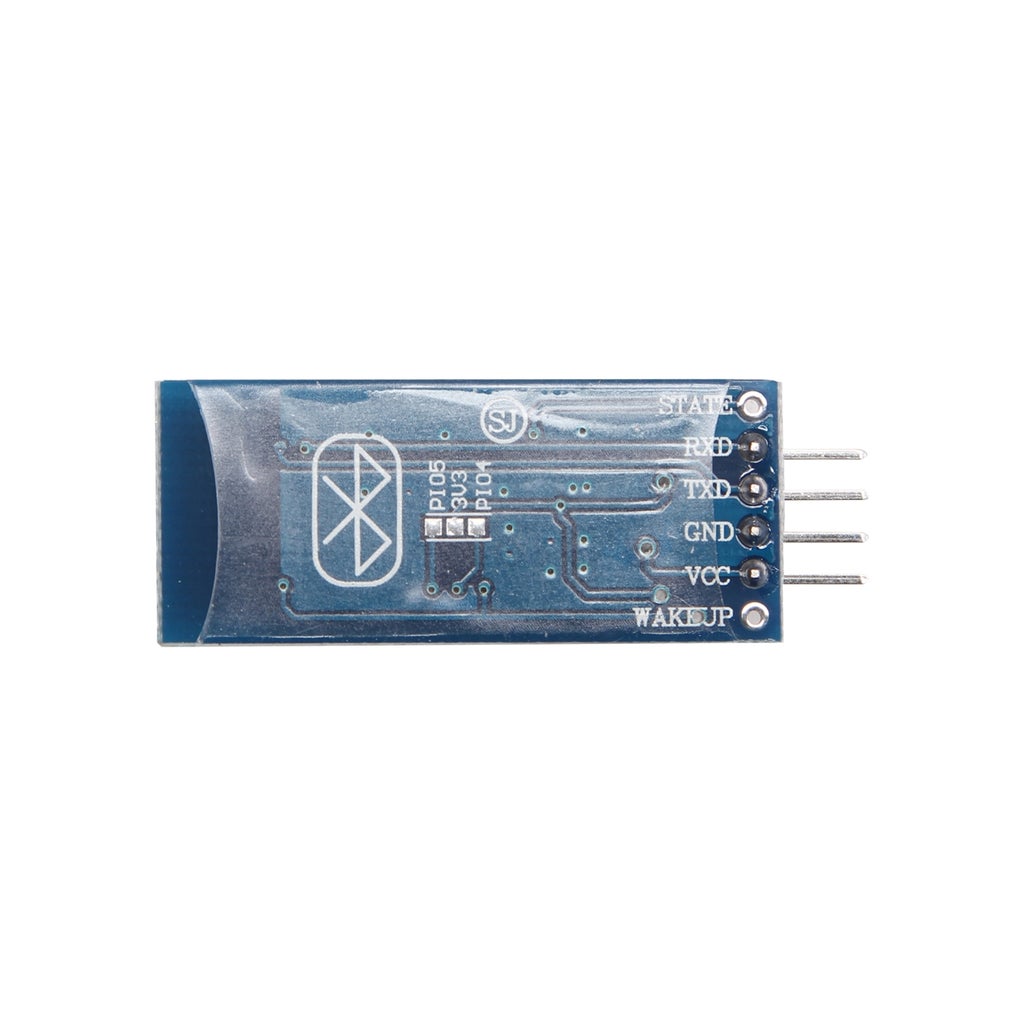
PINS: The pins found on the breakout board are,
KEY: This pin has to be pulled high to enter AT mode.
VCC: Indicated range is 3.6 to 6 volt. To be on safer side, you should connect it to 3.3 Volt.
GND: Ground.
RXD: Serial input pin.
TXD Serial output pin.
STATE: May or may not be connected to any pin. Supposedly outputs the Bluetooth connection status. This pin will not be needed.
Some of the breakout boards have EN pin or even WAKE UP pin instead of KEY pin. None of them seem to be connected to any pins of module. But that does not matter because we wouldn't need them anyway.
Once you identified the module, now it's time to enter the AT mode.
For HC05: Connect the Rx pin of the Bluetooth module to Tx pin of USB to TTL converter, and Tx pin of Bluetooth to Rx pin of converter. Also connect their ground but don't connect the Vcc yet. First you'll have to short the key pin with the Vcc. Connect key pin and Vcc together on breadboard, or any other way. After all other pins are connected, connect Vcc of bt module to USB to TTL converter's Vcc. Now the led on the module will blink at the interval of 2 seconds. That means it has entered the AT mode. If the led blinks faster then AT mode was not entered. Disconnect Vcc, check your circuit and try again. If it does not work then there's a chance that your KEY pin of the module is not really soldered to the KEY of the main chip, i.e. the 34th pin. You can check that with the help of multimeter.
If you use an arduino uno, then connect Rx pin of the Bluetooth module to pin 11 of Arduino Uno(supposedly same for arduino mega), and Tx pin of Bluetooth to pin 10 of Arduino. Also connect key pin of module to pin 9 of arduino and ground to ground, but don't connect the Vcc yet. You have to first power up the arduino, and then connect Vcc just like you did in case of USB to TTL converter.
For HC06: Just connect the Rx of module to Tx of usb-ttl converter and Tx of module. Connect ground and Vcc. The module is in AT mode. Didn't see that one coming, right? :P Turns out HC06 module is permanently configured to be slave and it is always in AT mode when not paired to any other device. So there is no confirmation led blinking that it is in AT mode like HC05 has. Just power up the module and pass the AT commands to modify the default settings.
Connection overview:
HC05 USB to TTL Arduino
Vcc Vcc Vcc
Rx Tx pin 11
Tx Rx pin 10
Gnd Gnd Gnd
key Vcc pin 9
HC06 USB to TTL
Vcc Vcc
Rx Tx
Tx Rx
Gnd Gnd
Step 3: If Key Pin Is Not Present or Not Connected


Only for HC05: As stated earlier, some models of the breakout board do not have the key pin, instead they have an EN (enable) pin or WAKE UP pin which may or may not be connected to any pin just like the STATE pin. In that case you'll have to solder a wire to the 34th pin of the bt module. I soldered a male header to mine but if you can't solder or don't want to, then you can just hold a wire (the pointy end of a male to male jumper wire would be convenient ) while connecting the Vcc to 5volt. Once the bt module is in AT mode, you can release the wire.
HC06 does not require key pin.
Step 4: Setting Up Connection


For HC05:
Once the module is in AT mode, open arduino. Go to tools>serial port>select the com port your USB to TTL converter is connected to (to find out, go to device manager of your pc>ports(COM &LPT)) . Now open the serial monitor. The bt module is now communicating at a baud rate of 38400. So change the baud rate to 38400 at bottom right corner of the serial monitor. Also change "no line ending " to "both NL & CR" found just beside the baud rate.
If you don't have Arduino IDE, then download Tera term(which is an excellent terminal emaluator). Open Tera term. A pop up window will open, Select Serial and choose the com port the usb to ttl converter is connected to. Press ok and a connection will be established. Now go to setup>serial port>set the baud rate to 38400. After setting up baud rate go to setup>terminal>change the newline to CR+LF from the drop down menu. Also check the local echo box under newline. Now the set up is complete.
If you use arduino (UNO/MEGA) board, then copy paste the following code, which is just a modification of Software Serial example included in arduino examples.
////////////////////////////////////////////////////////////////////////////////////////////////////////////////////
#include <SoftwareSerial.h>
SoftwareSerial mySerial(10, 11); // RX, TX
void setup() {
Serial.begin(9600);
pinMode(9,OUTPUT); digitalWrite(9,HIGH);
Serial.println("Enter AT commands:");
mySerial.begin(38400);
}
void loop()
{
if (mySerial.available())
Serial.write(mySerial.read());
if (Serial.available())
mySerial.write(Serial.read());
}
/////////////////////////////////////////////////////////////////////////////////////////////////////////////////////////
Upload the code to the arduino board, once the code is uploaded, open Serial monitor, change "no line ending " to "both NL & CR" at the bottom, close it and disconnect arduino board from usb. Now again reconnect arduino to usb,connect vcc of bluetooth module to arduino 5volt, and open serial monitor. The led on the module should blink at the interval of 2 seconds. That means it has entered the AT mode. Now you are ready to enter AT commands.
For HC06:
Now there is a small drawback for HC06, it does not wait for any termination character for each AT command entry. Instead, it acts to whatever character you entered after one second. Hence, if you are not able to complete a command entry within a second, it will be ignored. Because of this behavior, it may be extremely difficult to do manual entry configuration using Windows Hyper-terminal software. Terminal software that allows batch sending of multiple characters must be used. I found that arduino works fine. On the other hand, if you use Tera term you have to write down the AT commands in a notepad, than copy-paste it to Tera term. Right clicking on Tera term console will automatically paste the copied line and execute immediately.
So once the module is connected to usb-ttl converter and powered up, open arduino, select the usb-ttl com port, set baud rate to 38400. No other settings have to be applied unlike HC05. And for Tera therm, select appropriate com port, go to setup>serial port>set the baud rate to 38400, go to setup>terminal>check the local echo box and everything is set.
Step 5: AT Commands

For HC05: Type "AT" (without the quotes) on the serial monitor and press enter. if "OK" appears then everything is all right and the module is ready to take command. Now you can change the name of the module, retrieve address or version or even reset to factory settings. To see the default name, type AT+NAME. The name will be prompted, by default it is HC-05 or JY_MCU or something like that. To change the name just type AT+NAME=your desired name.
Here is an important note, if the key pin is not high, i.e. not connected to Vcc while receiving AT commands(if you did not solder the wire and released it after the module entered AT mode), it will not show the default name even after giving right command. But you can still change the name by the command mentioned above. To verify if the name has really changed, search the device from your pc/mobile. The changed name will appear. To change baud rate, type AT+UART=desired baud rate. Exit by sending AT+RESET command.
Most useful AT commands are
AT : Ceck the connection.
AT+NAME : See default name
AT+ADDR : see default address
AT+VERSION : See version
AT+UART : See baudrate
AT+ROLE: See role of bt module(1=master/0=slave)
AT+RESET : Reset and exit AT mode
AT+ORGL : Restore factory settings
AT+PSWD: see default password
More detailed AT commands are given in the 1st pdf.
For HC06: On arduino serial monitor type "AT" (without the quotes) and press enter, "OK" will confirm AT mode. Unlike HC05, you can't see the default name or baud rate. You can only change them. To change name type AT+NAMEDESIRED NAME, notice that there should be no space between the command and name. The module will reply OKyour set name. For example, AT+NAMEPROTOTYPE will set the name to PROTOTYPE. To change baud rate, type AT+BAUDX, where X=1 to 9.
1 set to 1200bps
2 set to 2400bps
3 set to 4800bps
4 set to 9600bps (Default)
5 set to 19200bps
6 set to 38400bps
7 set to 57600bps
8 set to 115200bps
so sending AT+BAUD4 will set the baud rate to 9600.
For Tera Term write down the commands somewhere else and paste it on the console by right clicking. No need of pressing enter. The command will be executed immediately and confirmed.
HC 06 AT commands are limited, all I could find are given here.
AT : check the connection
AT+NAME: Change name. No space between name and command.
AT+BAUD: change baud rate, x is baud rate code, no space between command and code.
AT+PIN: change pin, xxxx is the pin, again, no space.
AT+VERSION
More details in 2nd pdf.


