

Introduction: ATTiny85 Connects to I2C OLED Display - Great Things Can Be Small


I recently came across a tiny OLED display which I also used for another project. This time I thought a tiny display can be driven by an [AT]Tiny processor :).
The vision is - "create a tiny gaming machine"
Well the first step is taken. At least something is happening on the display. Feel free to suggest a game idea.
Parts we need
- ATTiny85 break out board - CoPiino Connectable BrainZ from ebay ($6)
- OLED Display with SSD1306 driver from ebay ($5)
- AVR Programmer USBasp from ebay ($4)
- 5V/3.3V regulated voltage source
- some jumper wires
- Arduino IDE
Attention: The display module I used had an operation range from +3.3V to +5V. So I could easily connect +5V. You need to carefully check if your display also supports +5V otherwise use a regulated +3.3V power source !!
Edit:
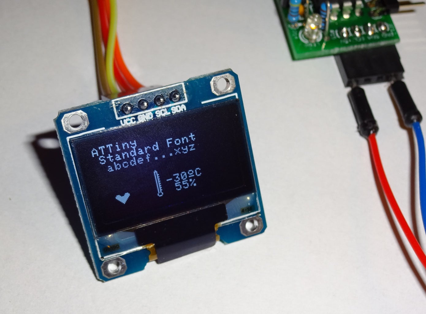
- uploaded additional target project => demo for font and icons
- uploaded some pictures for font and icons
Step 1: Soldering the Board


The CoPiino Connectable BrainZ comes as soldering kit. So it needs some soldering. All parts are through-hole and can be soldered old fashioned with soldering iron.
Scope of supply:
- PCB 21x28mm with M3 fixing hole
- 1x ATTiny85-20PU
- 1x LED 3mm yellow
- 1x Resistor 1k
- 3x Resistors 4.7k
- 2x Capacitors 100nF
- 1x pin header angled 1x4
- 1x pin header angled 1x5
- 1x Straight header
- 2x3 (AVR ISP)
- 1x Receptacle angled 1x4
It took me 20mins to solder all parts.
Step 2: Programming the CoPiino Connectable BrainZ

This step is pretty forward. The required source code is attached to this step. All files need be extracted.
Included files are
- ATTiny_OLED_Bouncing_Ball.ino
- SSD1306_minimal.cpp
- SSD1306_minimal.h
- TinyWireM.cpp
- TinyWireM.h
- USI_TWI_Master.cpp
- USI_TWI_Master.h
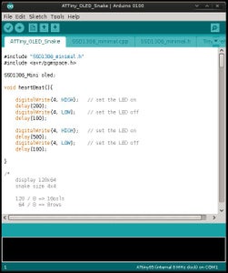
1. With the Arduino IDE we open the ATTiny_OLED_Bouncing_Ball.ino
2. We need to use the menu "Sketch" - "Add File ... " and add all other files one by one
3. Connect the CoPiino Connectable BrainZ to the USBasp (see notes below)
4. Connect USBasp preferably to a USB hub
5. Arduino IDE: Compile and Upload
6. Check for completed Upload
7. Disconnect USB
8. done
notes:
For connecting the USBasp to the CoPiino Connectable BrainZ we apply these pin connections
ISP10PIN to ISP6PIN
Pin 9 to 1 [MISO]
Pin 2 to 2 [VCC]
Pin 7 to 3 [SCK]
Pin 1 to 4 [MOSI]
Pin 5 to 5 [RST]
Pin 2 to 6 [GND]

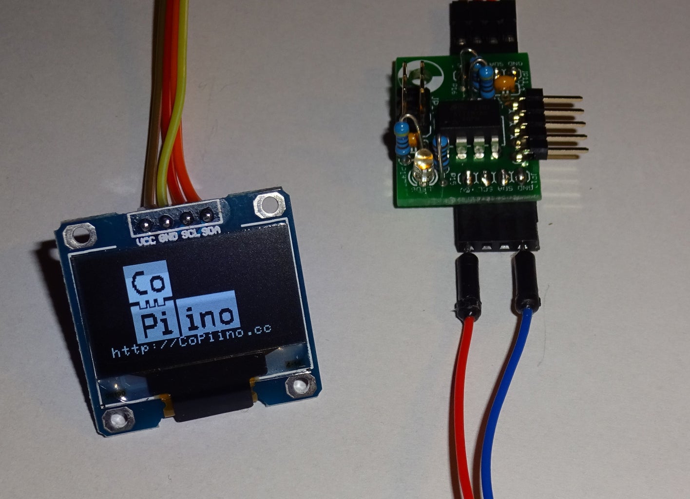
Step 3: Connect and Run

The display will be connected through I2C / TWI which are the signales SDA/SCL. Additionally we draw VCC and GND from the CoPiino Connectable BrainZ to the display. So all toghether we have 4 single cables between display and BrainZ.
Attention: The display module I used had an operation range from +3.3V to +5V. So I could easily connect +5V. You need to carefully check if your display also supports +5V otherwise use a regulated +3.3V power source !!
We then use our 5V/3.3V regulated power source and inject GND and VCC into the appropriate pins at the BrainZ module.
You will be enlightened by the nice moving ball in a grid on the display.
Congrats!
Now its time to make the next step. Any gaming idea that can be implemented?

Participated in the
Mind for Design


