

Introduction: Aergia: Android Controlled TV Remote(with Speech Recognition)


Have you ever faced this situation while sitting on your favorite spot on the couch or recliner, comfortably watching your favorite TV program? You're snugly tucked under the blanket, the air conditioning is pleasantly cool, the sun outside is shining it's delicate warm golden rays on the closed window, the air (from the air vents) is refreshing and gravity seems infinite...... It's almost like nature doesn't want you to get off your couch.......
Then all of a sudden a horrible commercial pops up on the TV and you desire to switch the channel immediately. However, the TV remote which is located just beyond your arm's length seems to be many miles away and you do not have the energy nor the will power to reach for it. You then look with disappointment at your aging Android phone which is near you and hope that you could use it to control your TV. If you're like me, then you're faced with this situation quite often......... in fact EVERYDAY!
As a solution to this quite serious problem, I have devised 'Aergia' (named after the Greek goddess of laziness and sloth), a gadget which with the help of an Android phone can control my TV, set top box, stereo or any other device which uses an IR remote. Besides, this device can be built at a cost of just $20 and the skills required to build it are bare minimum (basic knowledge about electronics and the Arduino IDE).
So let's get lazing....... I mean building!
Step 1: Parts Needed


The following parts are needed to build this project :-
Supplies :
1. Arduino Uno
2. Bluetooth Module (I have used the HC-05)
3. IR LED
4. IR Receiver
5. Resistors (1pc 100 ohms, 1pc 10K ohms and 1pc 20K ohm)
6. PCB
7. Electrical Wire
8. 9v Battery
9. 9v Battery Snap
10. Male Header Pins (both straight and bent)
11. Steel Wire
12. Insulation Tape
13. Heat Shrink
14. Project Enclosure
Tools :
1. Soldering Wire
2. Soldering Iron
3. Soldering Wax
4. Drill
5. Hacksaw
Step 2: Preparing the Project Enclosure


In this step you will drill the holes on the project enclosure to mount the Arduino, IR LED and IR Receiver.
A lot of the auto-makers these days follow a design language. For instance, the Lincolns which look like a baleen whale, and the BMWs which look like a daredevil pig hat has smashed its nose against a wall. I too follow a design language in my projects which I call the 'Lunch Box' Design. I have carried forward the same design language to this instructable as well and hence used a 'Lunch Box' as my project enclosure.
1. Drill four holes at the bottom of the project enclosure to secure the Arduino Uno.
2. Drill a hole on the left wall of the enclosure big enough for the USB port of the Arduino to protrude out of the enclosure (Refer to pic. 1).
3. Drill a hole on the right wall for the IR Receiver (Refer to pic. 2).
4. Drill four holes on the right wall for the IR LED stem. Two of the drilled holes are for the IR LED, while the other two are to anchor the IR LED Stem to the project enclosure (Refer to pic. 2).
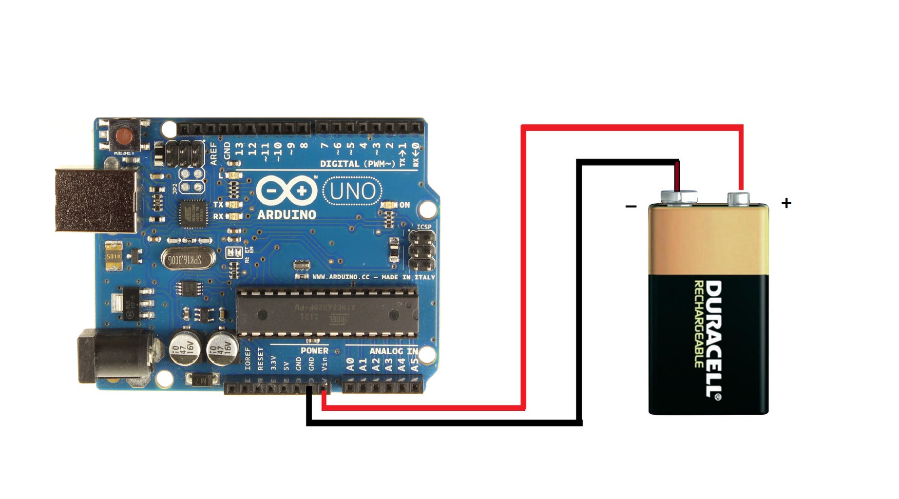
Step 3: Power Supply Circuit


The Arduino Uno used in this project is powered by a 9v battery. The Arduino has an on board regulator which can receive an input voltage within the range of 6v - 20v. Due to this, we do not need any additional circuit to regulate the input voltage to the Arduino when connected to a 9v battery.
1. Solder the bent Male Header Pins to the two wires of the 9v battery snap.
2. Cover the soldered points on the wire with insulation tape or heat shrink. The header pins soldered to the battery snap must look like pic. 2.
You are now done with the power supply circuit for the Arduino.
Step 4: IR Receiver Circuit


The IR Receiver is used to detect and decode the IR pulses sent from the TV remote. The decoded IR signals are then stored in the Arduino Uno.
1. Carefully bend the three leads of the IR Receiver backwards at a right (90 degrees) angle (Refer to pic. 2 and pic. 3).
2. Solder three wires to the leads of the IR Receiver. Ensure that you insulate each of the leads of the IR Receiver so that there no possibility of the pins shorting in case they come in contact with each other (Refer to pic. 4).
3. Solder the bent Male Header Pins to the other end of the wires. The completed circuit must look like pic. 1.
Step 5: Bluetooth Transceiver - Part 1: Bluetooth Module


The Bluetooth Module enables the Arduino to connect and communicate wirelessly with the Android phone. I strongly suggest to purchase a Bluetooth Module which is soldered to a breakout board. Purchasing only the Bluetooth Module without the breakout board means that you will have to do the tricky soldering part which could damage the module if it is not done witht the right tools. If you have only purchased the Bluetooth Module, visit Step 4 of this instructable for details about the soldering.
If you have purchased the Bluetooth Module with the breakout board but do not have the Female Header Pins to connect to the module, then you can use the following Top Tip: Briefly heat the ends of the wire over a candle to partially melt and loosen up the insulation on the wire. Then force each of the wires into the Vcc, Gnd , Tx and Rx pins of the Bluetooth Module.
Connect the Female Header Pins to the Vcc, Gnd , Tx and Rx pins of the Bluetooth Module.
Step 6: Bluetooth Transceiver - Part 2: Level Shifter Circuit


The Arduino Uno has a serial input/output of 5v through its pins, whereas the Bluetooth Module operates at 3.3v logic. Due to this, a voltage divider circuit ( level shifter ) is required to convert this 5v output to 3.3v.
1. Cut a small piece of PCB and solder two Male Header Pins (Straight) to it. Refer to pic. 2
2. Solder the 10K ohms and 20K ohms resistors according to the circuit diagram in pic.5
3. The final completed circuit should look like one in pic. 4
You have now completed the Bluetooth Transceiver.
Step 7: IR LED Stem


The decoded IR pulses stored in the Arduino is transmitted back to the TV using the IR LED.
1. Solder two long electrical wires of equal length to the leads of the IR LED (Refer to pic. 2).
2. Cut a length of the steel wire slightly longer than the electrical wire.
3. Firmly wrap the steel wire to the two electrical wires. This creates a flexible stem for the IR LED which can be directly positioned in front if the IR Receiver of the TV (Refer to pic. 1 and pic. 3).
4. Cut a small piece of the PCB and solder a Male Header Pin and the 100 ohms resistor to it. The resistor will connect to the positive lead of the IR LED while the Header Pin will connect to Arduino Pin 3 (Refer to pic. 4).
Step 8: Final Assembly


Now that all the component modules are complete, you can begin the final assembly of 'Aergia'.
1. Place the Arduino Uno in the project enclosure and fasten it with screws or zip tie (Refer to pic. 1).
2. In order to connect the IR Receiver module, draw the three wires of the IR Receiver through the hole drilled in the project enclosure. Connect OUT pin and Vcc pin of the IR Receiver to Arduino pin 11 and +5v pin respectively. Connect the Gnd pins of both the IR Receiver and Arduino with each other (Refer to pic. 2 ,pic. 3 and pic. 4).
3. For attaching the IR LED stem , connect the Male Header Pin having the 100ohms resistor to pin 3 of the Arduino (Refer to pic. 5). Connect the Header Pin having a wire to the Gnd pin of the Arduino. Draw the two wires of the Header Pins through the holes drilled in the project enclosure and use wire connectors on the ends of the wire (Refer to pic.6). Connect the positive wire of the IR LED to the wire which connects to pin 3 of the Arduino. Connect the negative wire of the IR LED to wire which connects to Gnd pin (Refer to pic.7 and pic. 8).
4. Connect the Tx pin of the Bluetooth Transceiver to Arduino pin 6. The Rx pin of the Bluetooth module connects to the level shifter between the 10k ohms and 20k ohms resistors. The 10k ohms resistor of the level shifter connects to Arduino pin 7 and the 20k ohms resistors connects to the common ground pin of the Arduino. The Vcc pin of the Bluetooth module connects to the 3.3v output pin of the Arduino. The Gnd pin of the Bluetooth module connects to the Gnd pin on the Arduino. Place the Bluetooth Trasceiver circuit inside the enclosure (Refer to pic.9 and pic. 10).
5. Connect the positive wire from the Power Supply circuit to the Vin pin and the negative wire to the Gnd Pin of the Arduino. Then place the 9v Battery Snap into the project enclosure (Refer to pic. 11, pic. 12 and pic. 13).
The hardware assembly of 'Aergia' is now completed.
Step 9: Programming the Arduino

Before you can program the Arduino Uno, you must first install the IR library (by Ken Shirriff) for handling the IR Receiver and IR LED.
These are the steps to install the library :-
1. Download the Tiny GPS library for the Arduino (link).
2. Extract the zip file to the folder: " Libraries/Documents/Arduino/libraries "
3. Now you would see the library under " Sketch --> Import Library " in the Arduino IDE.
4. You can now proceed with programming the Arduino Uno.
The following is the source code for the Arduino. Download the code below, open it in the Arduino IDE and upload it to the Arduino.
Attachments

Step 10: Android Bluetooth Remote App


I have created an Android app which acts as a universal bluetooth remote. It helps the Android phone communicate with 'Aergia'. In addition to all the basic buttons an IR Remote has, the app also features a voice recognition system and 12 user programmable buttons.
The app is attached to this page and must be downloaded and installed on your Android Phone.
The following are the components and buttons of the Bluetooth Remote App :
- Speech Recognition Button : Click on this button and speak out the command button clearly. The voice interpreted by the app is displayed on a small label above this button.
- Power Button : Used to turn on/off the TV.
- Numpad : The numpad contains buttons numbered from 0 to 9. It also contains the Dash Button for entering double/triple digit channel numbers and the Previous Channel Button for navigated back to the previous channel.
- D-Pad : The Directional Pad (D-Pad) has 5 buttons to navigate the TV's channel/settings menu.
- Volume and Channel Buttons : The Volume Buttons are used to increase and decrease the volume of the TV. The Channel Buttons are used to switch channels.
- 3-Buttons Array : This array of buttons contains the Mute Button, Menu Button and Back Button.
- 12 Programmable Buttons : These are 12 buttons which you can configure according to the various functions your TV's IR remote offers.
- Bluetooth Configuration Section : This section contains the text box for entering the MAC address of your Bluetooth module. It also contains the Connect Button. The Bluetooth MAC address must only be entered once while opening the app for the first time. The next time you open the app, it will automatically connect to the Bluetooth module without the need of entering the address again.
- Settings Button : The Settings Button is used to configure all the other buttons of the app so that 'Aergia' can work with your TV.
Attachments
Step 11: 'Aergia' in Action!


Having built the 'Aergia', you can begin using it with your Android phone and TV.
Kindly follow these steps for using 'Aergia' :-
1. Power on the 'Aergia' by connecting a 9v battery to the battery snap.
2. Turn on the bluetooth in your Android phone and pair with the 'Aergia'.
3. Open the Android app.
4. If you are using the 'Aergia' for the first time, then you must enter the Bluetooth MAC Address of the bluetooth module in the App's textbox. In order to obtain the MAC Address, download the App in this link and follow the instructions on its webpage. You will also have to setup the app for your TV. To setup the app, click the Setup button in the Android App.
5. The app now turns into setup mode and you can configure each button. In the setup mode, click on a button in the app, then while pointing the TV's IR Remote at 'Aergia', click on the corresponding button on the IR Remote.
6. Repeat the same steps for all the buttons on the IR Remote.
7. Once you have completed the app configuration, click on the Setup button once again to come back to the normal mode.
8. You can now use the app and 'Aergia'. Click on any button in the app and your TV will respond to it just like it would after receiving a signal from the Remote Control.
9. To use the Speech Recognition feature, click on the 'Microphone' button and clearly speak into the phone the command of the corresponding button on the remote.
Now that you know how to build 'Aergia', go ahead and build one yourself, and claim an 'eternal dibs' on your favorite spot on the couch!

First Prize in the
Home Technology Contest

Finalist in the
Battery Powered Contest

Participated in the
Remote Control Contest

Participated in the
Epilog Challenge VI


