

Introduction: (And Still Another Not So) Mini AT-TE Popsicle Stick Model


How about another armored walker from the Star Wars Universe? No, not the huge AT-AT but the smaller AT-TE..
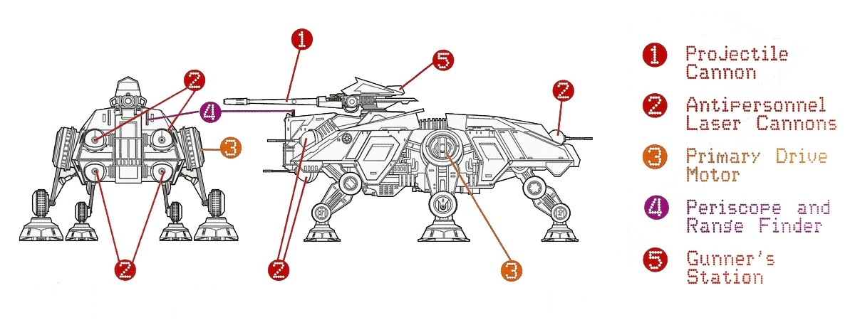
An acronym for All-Terrain, Tactical Enforcer, the AT-TE was the main battle tank used by the Galactic Republic during the Clone Wars. Propelled by six (6) articulated 'legs', the AT-TEs proved highly effective in rugged terrain and was capable of climbing steep walls. The 'tank's main armament consisted of six (6) laser cannon turrets mounted on the front and rear of the vehicle and a gigantic projectile cannon mounted on top of the driver compartment. The gunner of the projectile cannon sits exposed at the rear end of the weapon.
The build was a far cry from my first walker project, the AT-ST, not just because of the size of the AT-TE, but the complexity as well. Surprisingly though, it took me just a week to come up with the finished model. More surprising was that the build was made without the use of Dremel's high speed cutter attachments. Activities were purely sanding, shaping and gluing.
Anyway, I hope everyone enjoys this instructable!
Step 1: Materials and Tools


A lot of tongue depressor-sized popsicle sticks were used for this build. The front and rear crew and passengers cabin was built from eighteen (18) pieces of
popsicle sticks laminated together using Elmers white glue. Majority of the round subcomponents like the drive shaft and joints where from dowels and various sized popsicle sticks carved and sanded to look like dowels. Most of the smaller parts were from my spares box including leftover pine needles from my snowspeeder project.
Tools used for the project were:
- Dremel 3000 with the following attachments and accessories:
- Dremel's workstation and flex tool shaft
- Coarse and Fine Drum sander
- Fine disc Sander
- Standard & reinforced cut-off wheel
- #9936 structured tooth tungsten carbide cutter
- #85602, #85422 & #85922 Silicone Carbide grinding stone
- #953 Aluminum Oxide grinding stone
- ball-shaped grinding stone
- X-acto cutter with #11 blade
- Fine tweezers
- Mechanical pencil
- Ruler
- Various Clamps
- Elmers White Glue
- Cutting mat
Step 2: Schematics and Images


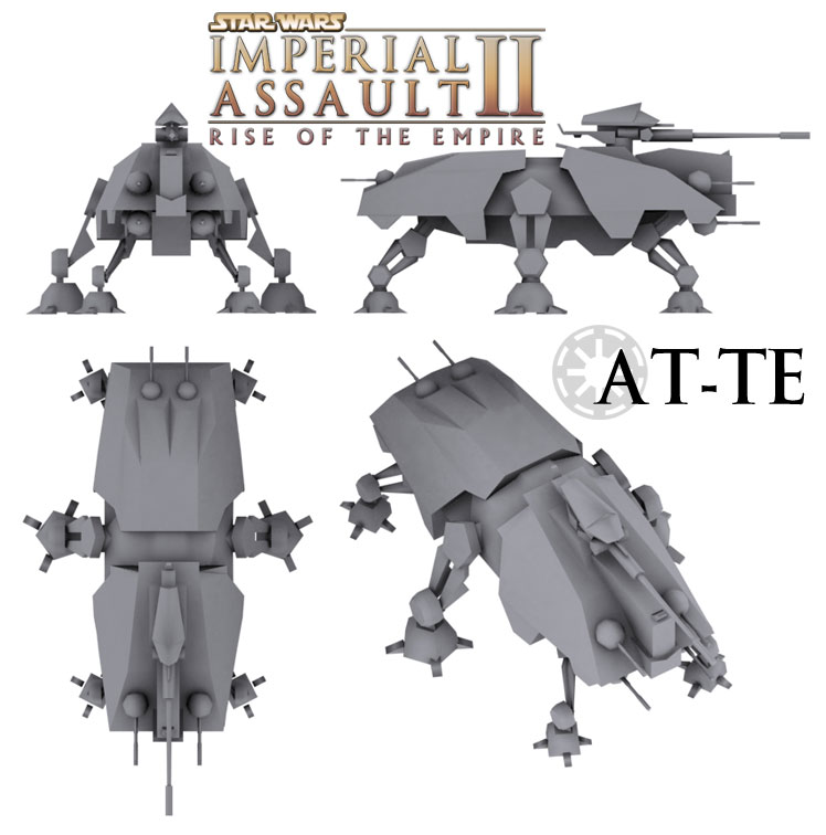
The main schematics I used for the build was from vignette2.wikia.nocookie.net. I superimposed my original Millennium Falcon and AT-ST schematics to get an approximate scale for the AT-TE. Google images keywords was "AT-TE". Below are the URL's of images and schematics I referenced for this project:
http://vignette2.wikia.nocookie.net/starwars/image...
http://vignette4.wikia.nocookie.net/starwars/image...
http://vignette2.wikia.nocookie.net/starwars/image...
http://imperialassault.com/rote/files/PR/atte_new...
I've also added a .pdf file of the plans I used in this project. No words can express my appreciation to the folks providing those amazing images. More power to everyone!
Attachments

Step 3: Crew and Passenger Cabin


The AT-TE's 'buglike' configuration was broken down into three (3) main sections, the front, driver's cabin, the flexible, middle section and the rear passenger compartment. Eighteen (18) layers of tongue depressor-sized popsicle sticks made up the front and rear segments of the vehicle. For the drivers cabin, four (4) layers comprised the central driving station with the remaining fourteen (14) layers (seven per side) comprising the bulk of the front module.
The vehicle's profile was traced on the popsicle stick using the schematics as reference. After cutting and carving a pattern for the driver's cabin using a combination drum and disc sander, the remaining layers were glued and allowed to harden. I found it easier to work on carving an entire block using the single pattern as guide. A reinforced cutting wheel proved useful in cutting slots and right angles on the block of wood. The angled sides of the front compartment, was carved using a fine-grit drum sander and finished with a fine disc sander.
Similar steps were done for the rear passengers compartment with an initial pattern cut from a single popsicle stick and glued with the rest of the seventeen (17) layers before grinding and sanding using a combination of drum and disc sander. A #9936 structured tooth tungsten carbide cutter was extremely useful in carving huge chunks from the single block before fine sanding with either a drum or disc sander attachment.
At this point, a large dowel was used for the vehicle's six (6) laser turrets. The dowel was initially rounded at one end using a combination drum/disc sander attachment on a moto tool. Next, a slot was made using a reinforced cutting wheel. To complete the round shape, a fine-grit drum-sander attachment was used to carve the half-circle while the piece was still connected to the dowel. An X-acto cutter was used to detach the circular 'turret' from the dowel.
Fabricating the turrets were necessary to provide a guide to carve the two (2) gun mounts at the rear passengers compartment.
For the mid-section, twelve (12) layers were laminated and sanded to form a single block. The contour for the mid-section was traced from the trailing edges of the front, driver's compartment and the rear passengers compartment. The final shape of the mid-section was carved using a combination #9936 structured tooth tungsten carbide cutter, reinforced cutting wheel and drum/disc sanders attachment on a Dremel 3000 with flex shaft.
After ensuring a snug fit with the finished front, driver's compartment and the rear passenger compartment, the mid-section was glued to the front and the rear modules completing the body of the AT-TE.
Step 4: Propulsion System


For all the circular pieces of the vehicle particularly the circular 'feet' and articulating 'joints', various sized dowels were used. Since I had
my fair share of different sized dowels from previous builds, I sourced the 'fabricated' dowels for the central, main drive shaft, central lower joint and smaller front and rear feet from my spares box. It was a matter of slicing using a reinforced cutting wheel attachment and shaping with a fine-grit drum sander attachment for the hourglass-shaped drive shaft and bell-shaped front/rear feet of the walker.
Seven (7) layers of cut, tongue depressor-sized popsicle sticks were laminated and shaped into a dowel for the walker's middle legs and upper, central articulated joints. A depression was made on the central articulated joints using a 'ball-shaped' grinding wheel attachment on a moto tool. The depression was vital to provide a means to connect to a project to fabricate a Low Altitude Assault Transport/carrier (LAAT/c). More on this in the future.
Dowels brought from a local crafts shop provided the parts for the front and rear, lower and central articulated joints.
Spares from tongue depressor-sized popsicle sticks provided the materials for the two (2) central 'legs'. These were cut to a small coffin-shaped parts and sliced in half using an X-acto blade.
For the thinner front and rear 'legs', thin coffee stirrers were cut using an X-acto blade. Similar to the bigger central legs, the pieces were sliced since images of the walker depict legs with a space in between.
All the circular and tiny pieces were set aside for the final assembly.
Step 5: Weapons System


I really got a kick building the single, massive projectile cannon of the AT-TE. It was, after all, the most distinguishing feature of the AT-TE next to the six (6) unusual propulsion 'legs'.
The length of the gun barrel was traced on a toothpick using the wikia schematics as reference. A fine-grit drum sander attachment on a moto tool was used to shape the tapering barrel and flash suppressor/muzzle brake. A standard cutting wheel was used to cleanly detach the finished gun barrel from the excess toothpick.
Images show that the gunner's station mounts on top of the gun receiver, hence I opted to fabricate the two units separately.
Four (4) layers of spare popsicle sticks were laminated for the gunner's station. The distinct shape was traced on the single block using the wikia schematics as reference. Again, a standard cutting-wheel attachment on a moto tool proved useful in cutting angular shapes on the gunner's station. Bulk of the sanding and finishing was done with a combination fine-grit drum and fine disc sander attachment on a moto tool.
Two (2) layers of spare popsicle sticks were used for the gun receiver. Similarly, sanding and finishing was done with a combination fine-grit drum and fine disc sander attachment on a moto tool. I constantly checked that the width of the cannon's gun barrel fits the front end of the gun receiver.
The six (6) laser gun barrels were directly carved from toothpicks using a combination fine-grit sander and fine disc sander attachments on a moto tool.
A single singular piece for the projectile cannon mount was cut from a dowel using a regular cutting wheel attachment on a Dremel 3000 with flex shaft.
The projectile cannon's barrel was glued to the end of the gun receiver making sure that the barrel aligned with the receiver. A spare popsicle stick from my spares box was used to support the gun barrel while the white glue dries. Finally, the gunner's station was glued on top of the gun receiver using the schematics and images as reference.
This completes the section for the AT-TE's weapon systems.
Step 6: Completing the Build


The main drive shafts fabricated from the propulsion systems step were glued at the left and right mid-sections of the AT-TE. After the glue dried, the exposed ends of
the main drive shafts were sanded at an angle parallel to the angled body of the AT-TE.
Next, the rear laser gun turrets were sanded on one end using a fine disc sander attachment on a moto tool. The flat end increases the contact area of the rear laser gun turrets when glued to the cavities at the rear passenger compartment.
Similarly, the front top and bottom laser gun turrets got the same treatment before these were glued next to and below the driver's cabin. The disc-shaped projectile cannon mount was glued just behind the driver's station.
The pair of huge, central articulated joints were then glued to the exposed end of the angled drive shafts. Next, the sliced, central legs were carefully glued at the bottom edge of the drive shafts. Particularly tricky was gluing the central legs with a space in between. Laminated pieces from my spares box were used to support the pieces in place while the white glue dries.
The central lower joints were glued to the top of the huge, central legs of the walker. The central lower joints were then glued to the central legs with the vehicle temporarily propped up using popsicle sticks from my spare box. The walker should now be able to 'stand-up' when the glue has dried at this point.
For the front and rear legs and feet, the bottom front and rear articulating joints were first glued to the walkers front and rear feet. Next, the front and rear legs were glued to the center of each articulating joints providing a space between the two (2) leg pieces. Tiny, sliced toothpick pieces glued where the two (2) leg pieces join the articulating joints. The sliced toothpick parts provide additional surface bond between the leg and joint pieces.
Thin coffee-stirrers provided the link between the front and rear legs with the AT-TE's main body. The angles for these link was patterned from the wikia schematics. After these were cut using an Xacto knife, the top joints were glued to the end of the link opposite the angled end. The completed sub-assemblies were laid out on top of the schematics to estimate the angle of the legs in relation to the walker's body before applying white glue. The completed front and rear leg/feet sub-assemblies were then glued to the bottom front and rear part of the AT-TE. At this point, there was no need to prop up the entire vehicle since the central legs were able to support the entire walker.
Two (2) thin coffee-stirrers were laminated together for the rear differential. Although not illustrated in images gathered on the internet, the differential provided additional bonding surface area for the pair of rear 'legs'.
For added detail, a thin coffee stirrer was shaped using reinforced cutting wheel for the central stabilizer bar. A sliced toothpick provided the link between the walker's body and the central legs. Guard rails from pine needles and additional armor from spare popsicle sticks were cut and glued to the front and sides of the driver's canopy respectively.
And finally, the huge particle cannon was glued on top of the driver's station and the six (6) laser gun barrels glued at the front end of each laser gun turret respectively. Oh.. and I almost forgot. A thin coffee stirrer was also used for the tiny four (4) 'toes' in each of the walker's foot. The toes add a sense of lethality to the popsicle stick AT-TE.
Voila, a slow, lumbering AT-TE that seems to walk across my work table. I can't wait to build the carrier for this 'tank'. Cheers!


