

Introduction: Anti-Night Vision Device ¡¡¡CAUTION, NOT SAFE FOR EPILEPTIC OR SEIZURE PRONE INDIVIDUALS!!!


Have you ever been concerned about how many Instructables about making DIY Night Vision there are, and yet there are no Anti-Night Vision Instructables? How many DIY Drone tutorials are there, but no anti-Drones? How do we protect ourselves and our privacy from the proliferation of these new tools that have serious ethical implications.
What we are making today is a device which will disable augmented vision technologies. Infrared light is an illuminator for many visual augmentation systems. Thi device senses infrared light and triggers a very bright flashing visible light at a frequency which will induce confusion, disorientation, and nausea in the user (NOTE: this feature has undergone minor testing with mixed results).
We are going to build this in a series of steps, making and testing each component individually before integrating the whole system. There are three major components which we will connect together.
1) an Ambient Light Sensor
2) an Infrared Sensor
3) a High Power LED Flashing Circuit
Basic Arduino and Electronics skills will be useful.
Parts Needed:
- Arduino (any variety will work but we're using an Uno in this tutorial)
- Breadboard
- IR photoTransistor
- Power LED's
- photo resistor
- Several 10 ohm Resistors (or one 1 watt 2-4 ohm)
- 1x 10k
- 1x 100k
- 1x 2.2k
- 1x TIP120 transistor
- 1x LM317 Adjustable Regulator
- some sort of Power if you're going to deploy/make it mobile (ie. 9v battery and connector)
- Some source of IR light for testing (Candle, Lighter, Night Vision, Remote Control, etc)
Step 1: Ambient Light Sensor


This is a very simple part to start off with. It will sense the ambient light levels to see if the IR sensors will be activated. We will build a voltage divider with a Light Sensitive Resistor (LDR from here on out).
Reference the Schematic and images attached above
Attach the LDR between the Power Bus (+5v) and an empty row on the breadboard. Connect a 10k resistor between that row and ground. Then connect that row to Analog Pin 3. This will be our input pin in our code.
int brightnessPin = 3;
int brightness;
void setup() {
      Serial.begin(9600);
}
void loop() {
    brightness = analogRead(brightnessPin);
    Serial.print(“Ambient Light: “);
    Serial.println(brightness);
    delay(10);
}
This code will do an Analog Read and print it out in the Serial Monitor, it will give a sense of where we want your triggers to be. Turn off all the lights and look at the what the brightness value is. The number should get smaller as it gets darker. In my setup, I chose a value of 300 as the point to engage the IR sensors. Your number will be different. Write the range down. I got a range of ~100 with my lights off and 600 with the lights on.
Step 2: IR Sensor


The next step is to setup the Infra-red Sensors. We are using IR sensitive phototransistors. This is what is in your TV to sense remove control signals (this device can be triggered via remote control too!) or any IR communication technologies.
Reference the Schematic and images attached above
The IR sensors work similarly to the LDR, but HOW they actually work is completely different. (LINK: how do IR phototransistors work?) We'll wire them similarly. On the device there should be a flat side just like on an LED. That is our negative side. Connect the positive side to power and the negative side to a row on the breadboard and a 100k resistor to ground from that empty row. That row connects to Analog Pin 2.
int IRsensorPin = 2;
int IRsense = 0;
void setup() {
    Serial.begin(9600);
}
void loop() {
    IRsense = analogRead(IRsensorPin);
    Serial.print(“IR: “);
    Serial.println(IRsense);
    delay(10);
}
Turn off all the lights and flash some infrared light at the sensor, see what the values drop down to. Find their lowest point and add 10-20 to it. Write the range down. My sensors read 20 with the lights off and 1000 with full IR illumination.
Step 3: Combine the Sensors and Test
Next we will combine these two things we have connected to create a more intelligent interaction. We want to IR sensing to start when the Ambient Light Sensor falls below it's median value, lets say 300. And we want the IR to trigger when it rises above its low value, lets say 80, to give it a little wiggle room.
int led = 13; //We’re using the built in LED as a test
int IRsensorPin = 2; //Infrared Sensor Pin
int IRsense = 0; //IR Sensor Value
int brightnessPin = 3; //Ambient Brightness Pin
int brightness; //Ambient Light Value
float period; //Storing our Pulse Width Period
float hertz = 9; //Frequency of the flashing
float width = 0.2; //The PWM of our Flashing
float onTime, offTime; //Holders for actual Delay Times
void setup() {
    pinMode(led, OUTPUT); //Set Power LED as OUTPUT
    Serial.begin(9600); //Start Serial
    period = (1/hertz)*1000; //convert Hertz into millisecond delay times
    onTime = period * width; //calculate On time
    offTime = period * abs(1-width); //calculate Off time
}

void loop() {
    brightness = analogRead(brightnessPin); //Read ambient light level
   // Serial.print(“B: “); Serial.println(brightness); //print out value for DEBUG
    if(brightness < 300) { //start IR sensing IF ambient light level is below this level
        IRsense = analogRead(IRsensorPin); //Read IR sensor
       // Serial.print(“IR: “); Serial.println(IRsense); //print out value for DEBUG
        if(IRsense > 80) { //if Infrared sensor detects IR light
            vertigo(); //Flash Light
        }
        else digitalWrite(led, LOW); //if not, keep LED OFF
    }
}

void vertigo() { //Flash LED

    bool flashing = 1; //a holder for the state of the flashing (true or false)
    while(flashing == 1) { //if flashing is TRUE
        //Flash LED at pre-determined rate
        digitalWrite(led, HIGH);
        delay(onTime);
        digitalWrite(led, LOW);
        delay(offTime);
	if(analogRead(brightnessPin) < 300) flashing = 1; //if ambient light levels rise (ie. you turn on a light) turn Flashing to FALSE
    else flashing = 0; //if they don't...keep on flashing
	}
}
Try it out! Get an IR light source (night vision, remote, IR LED, candle...etc), turn off the lights and try shining it on the sensor. Watch the Serial monitors to make sure everything is triggering OK, adjust values as needed.
Step 4: Illumination


The next step is to add some powerful LED’s to make this flashing actually effective. The flashing effect is called Flicker Vertigo and is “an imbalance in brain-cell activity caused by exposure to low-frequency flickering (or flashing) of a relatively bright light.”
We are using Power LED’s , which have to be treated slightly differently from a normal LED becasu they operate at much higher currents. There are plenty of great Instructables about them. For the scope of this project, we’re going to keep it as simple as possible. The Arduino isn’t able to supply enough current to drive a power LED directly, so we have to use an external power supply of some sort and a transistor to switch it. It is similar to working with motors. Also, because these LEDs are very sensitive to minute changes in voltage, so it is best to drive them using a Constant Current driver, which we are going to build.
Reference the Schematic and images attached above
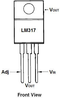
The Base of the TIP120 is connected to PIN 9 on the Arduino thru a 2.2k resistor to limit the current. The Emitter is connected to Ground and the Collector is connected to the negative side of the LED. The TIP120 acts as a switch by interrupting the connection to Ground. The LM317’s INPUT pin is connected to +9 volts (or whatever battery you’re using). The OUTPUT pin is connected to the ADJUST pin through a Current Sense Resistor. This is the control mechanism here. The value of that resistor dictates the amount of current the LM317 allows through it. The calculation is: R(esistance) = 1.25(voltageReference)/I(current in Amps). If we want 500mA, which is a good amount of current for these LED’s, the resistance would be 1.25/0.5, or 2.5 ohms. This is a great article on the LM317 as a constant current source with math for heat dissipation too. We’ll be using 4 1/4W 10 Ohm resistors in parallel, which will give us 2.5 Ohms because of this.
Make sure the Base of TIP120 is connected to PIN 9, and the led variable is set to 9 and then test the device again. It should be very unpleasant. Remember, all you have to do is turn the lights on to turn it off! Just make sure you remember where the light switch is.
This is the final code:
int led = 9; //HIGH power LED output
int IRsensorPin = 2; //Infrared Sensor Pin
int IRsense = 0; //IR Sensor Value
int brightnessPin = 3; //Ambient Brightness Pin
int brightness; //Ambient Light Value
float period; //Storing our Pulse Width Period
float hertz = 9; //Frequency of the flashing
float width = 0.2; //The PWM of our Flashing
float onTime, offTime; //Holders for actual Delay Times
void setup() {
    pinMode(led, OUTPUT); //Set Power LED as OUTPUT
    Serial.begin(9600); //Start Serial
    period = (1/hertz)*1000; //convert Hertz into millisecond delay times
    onTime = period * width; //calculate On time
    offTime = period * abs(1-width); //calculate Off time
}

void loop() {
    brightness = analogRead(brightnessPin); //Read ambient light level
   // Serial.print(“B: “); Serial.println(brightness); //print out value for DEBUG
    if(brightness < 300) { //start IR sensing IF ambient light level is below this level
        IRsense = analogRead(IRsensorPin); //Read IR sensor
       // Serial.print(“IR: “); Serial.println(IRsense); //print out value for DEBUG
        if(IRsense > 80) { //if Infrared sensor detects IR light
            vertigo(); //Flash Light
        }
        else digitalWrite(led, LOW); //if not, keep LED OFF
    }
}

void vertigo() { //Flash LED

    bool flashing = 1; //a holder for the state of the flashing (true or false)
    while(flashing == 1) { //if flashing is TRUE
        //Flash LED at pre-determined rate
        digitalWrite(led, HIGH);
        delay(onTime);
        digitalWrite(led, LOW);
        delay(offTime);
	if(analogRead(brightnessPin) < 300) flashing = 1; //if ambient light levels rise (ie. you turn on a light) turn Flashing to FALSE
    else flashing = 0; //if they don't...keep on flashing
	}
}
Step 5: Put It in a Cool Housing
This is my project housed in a McDonalds fry container. I used a 4 LED's instead of just 1 or 2 for more brightness. You can scale this project up as far as you want. I also used multiple IR sensors for detection in multiple directions.
Here is a janky cell phone video of it working.
VID_20150308_161414.mp4 from Kina Smith on Vimeo.


