

Introduction: Apple Floppy Amp


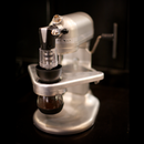


Found an old 5.25" floppy drive at a thrift store for $5.99. It reminded me of my Apple IIe childhood so I ended up buying it not knowing what I was gonna do with it. I'm a fan of anachronism ( Shameless plug: see retro hi-fi instructable)and needed a better housing for my computer stereo amplifier, so decided to combine the two.
Note: Electrical engineering knowledge not necessary for this project, I'm just a mechanical guy with a good understanding of "basic" wiring.
Step 1: Supplies!
PARTS - Note that not all are necessary and many can be substituted (e.g., you probably don't need the $30 volume pot, the one that comes with the amp works pretty well)
- Sonic Impact 5066 T-amp
- Apple PC 5.25 Floppy Drive
- 12V, 2A Power Supply (min 1.5A for substitutes)
- ALPS 50K Log Stereo Potentiometer (Volume)
- 1/4" Volume Knob
- 12VDC, 6A DPDT relay (or even SPST)
- 4x Speaker Terminals
- Stereo RCA Jacks
- Power Cord
- Misc Wiring
TOOLS:
Soldering Iron
Wire Cutters
Assorted Screwdrivers
Assorted Cutting Implements
Step 2: Modifying the T-Amp (Optional)


This step is totally optional as all the modifications listed here are simply to get the amp to "sound better." The stock amp out of the box already sounds pretty fantastic. All instructions for modifying the amplifier can be found here:
http://www.michael.mardis.com/sonic/start.html
I ended up performing the "Input Mods - Version 3"
Prior to attempting to stuff everything into the floppy drive I used a tupperware container as a prototyping enclosure. Things often go wrong when I play with electronics, so I wanted to make sure everything was happy before I started modifying the floppy enclosure. See the pics for a more detailed explanation.
Step 3: Gutting the Floppy Drive


The drive has a lot of heft to it! When I bought it, I thought, "This is gonna make a great project box for something."
I ended up removing most of the drive's internals, but kept the door lock mechanism intact, as I intended to use the flip of the lock as the ON/OFF switch.
See the pictures for more details on the gutting/cleaning process
Step 4: Fitting the Power Supply


This step is also optional, as it's perfectly acceptable to have an external power supply. I've got quite a selection of power supplies that I've collected over the years from outdated gear (i.e., cordless phones) and just happened to have a relatively flat one that fit in this case.
Since the power supply had the power prongs sticking out of the back of it, I first had to remove them by desoldering, then replaced the prongs with a power cord. If you're lucky, your power supply will already have a cord!
After some playing around, I found a nice spot for the power supply that required only minimal modification to the floppy drive's internal frame.
Step 5: Wiring the ON/OFF Switch


I finally caught a break in the project and was able to use a microswitch, that was part of the original floppy drive to turn everything on/off. The microswitch was a simple pushbutton momentary-type, that was pushed close when the floppy drive door lever was turned down.
I didn't check it out, but assumed that the microswitch wasn't rated for the 12V, 2A that the amp would be using . . . thus, the microswitch was used to control a relay. The relay was also something that I had laying around, they can be had at radio shack or even auto-part store for a few bucks (see supplies list)
Step 6: Fitting the Volume Knob/Pot


I wanted to minimize modifications to the floppy drive, but absolutely had to add a volume knob. I played with the idea of adding a disk sticking out the front of the drive (where a floppy would go), and simply thumbing the disk back and forth as a volume knob, but that proved too large of a mechanism.
Once I found a suitable spot for the volume knob, I had to make some room for it . . . which included some cutting, some bending, and of course some hammering!
Step 7: Add Input/Output


The back of the floppy drive provided a nice clean face to add speaker terminals as well as RCA input connectors. Before holes were drilled, I double-checked to see that the terminals would fit, and that I'd be able to route the wiring to the proper place!
Step 8: Button 'Er Up!


The last step actually took a good hour or so, trying to route wires so that they wouldn't be pinched when everything was enclosed. It's not much of a step, but I thought I'd add it in in hopes that you'd plan ahead for wire routing!
You also may be wondering where the actual amplifier was mounted! Unfortunately I didn't get a picture of it (I got lazy with pictures at the end), but it was just screwed down to the underside of the cast aluminum frame. Trust me it's under there (see comment on pic)!
I also removed the power LED from the amplifier board and added an extension wire to power the original LED that came with the floppy drive (disk-read light). This way, when the amp was switched on, the LED on the front of the floppy would also turn on.
Last but not least, I have to admit, this might be a pretty rough Instructable to re-create. My intentions for posting it were more to inpire others to find creative uses/reuses for things. I really liked the nostalgia I got from Apple's design and eventually figured out a practical use for it on my computer desk!
Participated in the
The Instructables Book Contest


