

Introduction: Arduino 7 Segment Clock


This tutorial is about making a clock using DS1307 real time clock module, Arduino and a 4 digit 7 segment led display.
Time and date are both displayed on the segment display as a result.
I made this project on a veroboard. You can use a breadboard if you want to just make a prototype.
Here is a good tutorial on how to use a breadboard if you are new to it and don't know how to solder.
Step 1: Gathering the Material


The following material is required:
- 1x Arduino Uno
- 1x 4 digit common cathode 7 segment
- 1x veroboard
- 1x DS1307 RTC
- 1x 3v lithium button cell for RTC
- Solder wire and soldering iron
- 2x pushbuttons
- 8x 100 ohm resistors
- 4x BC547 NPN transistors
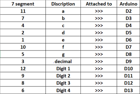
Step 2: Interfacing 7 Segment With Arduino


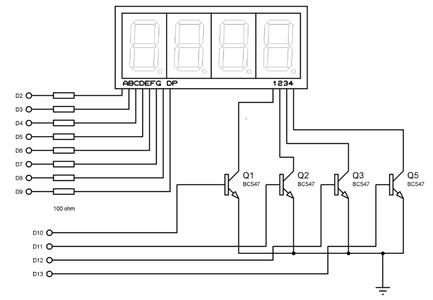
A 7 segment is a 7 segment because its made up of 7 leds to represent a digit from 0-9 when turned on in a specific manner. There is an 8th led for the decimal point.
Now suppose you want to display the number '5', then you turn on segments 'a', 'f', 'g', 'c', 'd'. By connecting to an Arduino you can turn these pins on and the rest off and display the number '5'. Make sure you connect the common cathode pin to the ground or any negative supply.
We are using a 4 digit display because we have multiple numbers to display. First lets connect our Arduino with the display.
Here are the connections. The digits are connected to Arduino via the transistors. Base is attached to digital pin of Arduino while the collector is attached to the common cathodes.
A multi digit number is printed onto the display digit wise. Lets say we want to print 7865, then we turn the first digit on and then the segments required to display 7. We then move on to the next digit and the process is repeated. Remember to turn only that digit on to which the number is displayed and turn the rest of the digits off, otherwise the number being printed will be displayed on whatever digit that is on.
Step 3: Interfacing RTC Module


Fortunately there is a library that helps us in reading time from the RTC.
Download it from here:
It contains the example ds1307 which has all the information on how to acquire time and date.
Insert the 3v battery before powering the module.
Connect the two push buttons to A0 and A1. These two buttons are there to set time in the future. One is to enter set mode and the other is to set time. There is no need for a pull down resistor as we will use the internal pullup resistors of Arduino.
Step 4: The Code
Here is the code.


