

Introduction: Arduino 7 Segment Countdown Timer
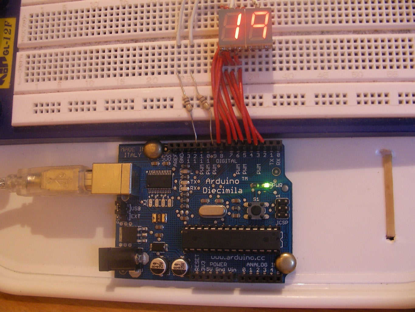


it counts down from 20 and lights up pin 13 LED when the timer is complete.
It uses no extra hardware which is usefull for low-cost projects.
It also features multiplexing to get the job done with only 9 pins altogether for the displays.
Step 1: Parts Needed
For this project you will need the following:
COMPONENTS:
1. An Arduino (any kind will do)
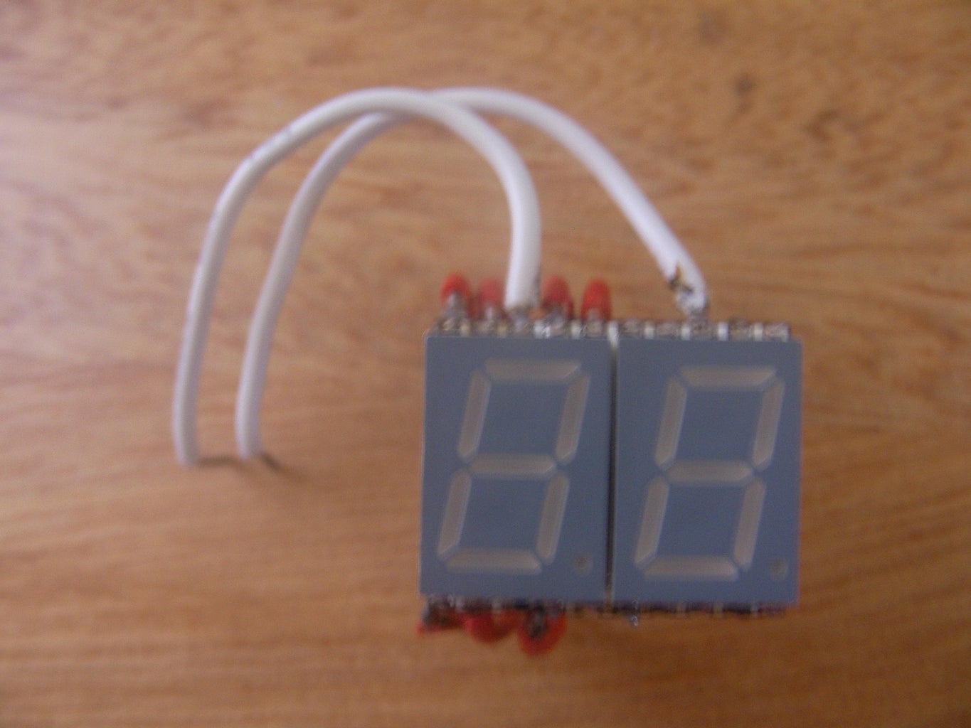
2. A dual-7 segmant display or 2 seperate 7 segment displays.
3. 2 Resistors (the values depend on your display)
4. About 50cm of non-stranded wire
TOOLS:
1. A soldering iron and solder. (My display was SMD so i had to solder wires to it for connection)
2. A fume extractor. (I really reccomend buying or making one as they are very helpful to you)
3. A wire stripper, or you could just use scissors
Step 2: What Is Multiplexing?


Multiplexing is when you control lots of LEDs with a few IO pins.
It is based on having to or more 7 segment displays and connecting them together, an example of what they would display is 00, 11, 22, 33, 44, 55, 66, 77, 88, 99.
But what we do in this case is control each GND (-) induvidualy which turns it into a multiplexed display.
We will switch displays every 0.5ms which gives us control of each display.
It is usefull when you are building a project with lots of components and are short of IO pins.
In this example, we will be controlling 2 7 segment displays with 9 IO pins.
If we don't use multiplexing, we will need 14 IO pins to control the whole thing.
Step 3: The Build

This project is quite complicated so you will need basic electronic skills.
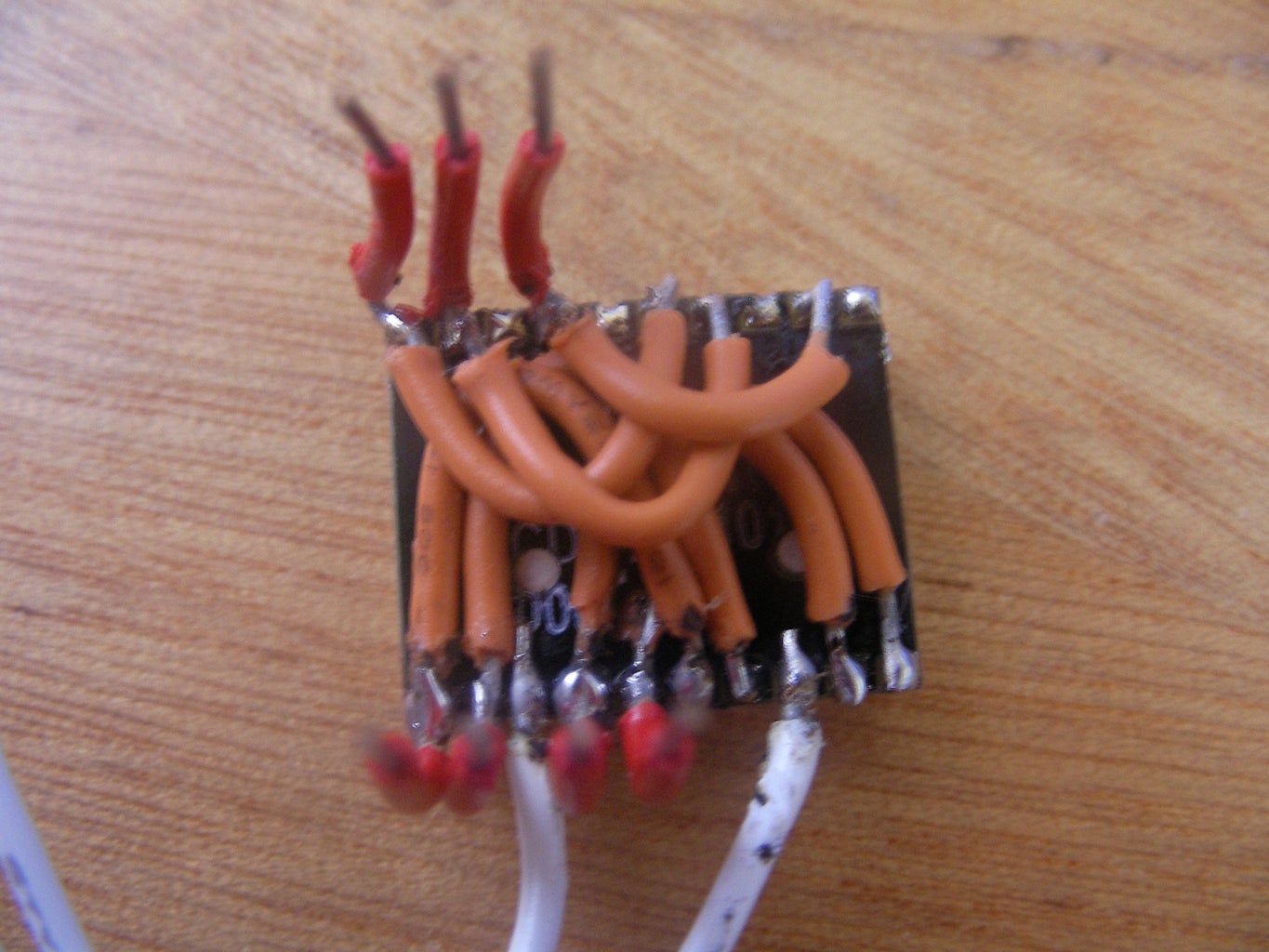
First you will have to solder wires on the back to make the multiplexing circuit.
This can be done on a breadboard if your display is not SMD.
Secondy, solder on jumper wires to plug the display into the breadboard.
Thirdly, connect wires from the breadboard to the Arduino in this sequence:
Segment A: pin 7
Segment B: pin 8
Segment C: pin 4
Segment D: pin 3
Segment E: pin 2
Segment F: pin 6
Segment G: pin 5
Gnd1 via resistor: pin 11
Gnd2 via resistor: pin 9
Step 4: The Programming!!!
THE CODE TIME!!! YAY!
This is my favourite part of any project, because i know it is almost complete!
I have wrote 2 programs: one that counts down from 20, and another that scrolls the message"Arduino" across the displays.
I will explain some of it in the code, just so you can understand it a bit better.
In the beginning, it initialises all the pins, and sets a few variables.
In the Void Setup, it sets up all the pins as outputs.
It also contains lots of FOR LOOPS, which are used when the LEDs are switched.
In the Void Loop, it sets pin 13 high and fades the 2 gnd pins on and off, which displays a pulsing 00.

Participated in the
Arduino Contest


