

Introduction: Arduino ATtiny2313 Programming Shield


![Artoo [R2] (ATtiny2313 Wall Avoiding Robot)](https://content.instructables.com/FQ5/VD0W/HH2VMVRB/FQ5VD0WHH2VMVRB.jpg?auto=webp&crop=1%3A1&frame=1&width=130)
Today, I made a small 3x3x3 LED cube with an ATtiny2313 that I had from about 2 weeks ago. Whenever I had to reprogram the LED cube when I thought of more awesome patterns, I had to get out my breadboard and then wire up everything again referring to pin-outs of ATtiny2313 and make sure everything is connected right and then finally upload the new code.
So I went on to eBay and amazon searching for something to program these chips as I was planning on using these chips a lot in the future. After spending about an hour I just realized I was wasting my time as there was no way I was going to spend about 20-30 dollars on a simple shield.
After thinking for a bit, I decided to make a simple and easy to make, ATtiny2313 programming shield, after I made it, all I needed to do to recode any of my attinys' is to just put it in the programming shield and just in a few clicks you have your code uploaded! No need to worry if everything is wired right and make sure there are no short circuits or anything that can short out the chip and fry it or anything else of that sort.
So now in this instructable I will show you how to build one of these shields for yourself!
It costs almost nothing and takes only about 30mins or so to make it.
So lets get started!
Step 1: Materials
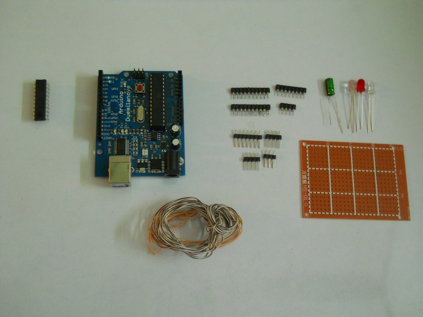
- Protoboard
- 10 Micro Farad Capacitor (or similar value)
- 2 LED's
- A couple of wires
- A single row pin header strip
- A single row female pin header strip
- Soldering Iron
- Solder
- Glue Gun (Or just good glue)
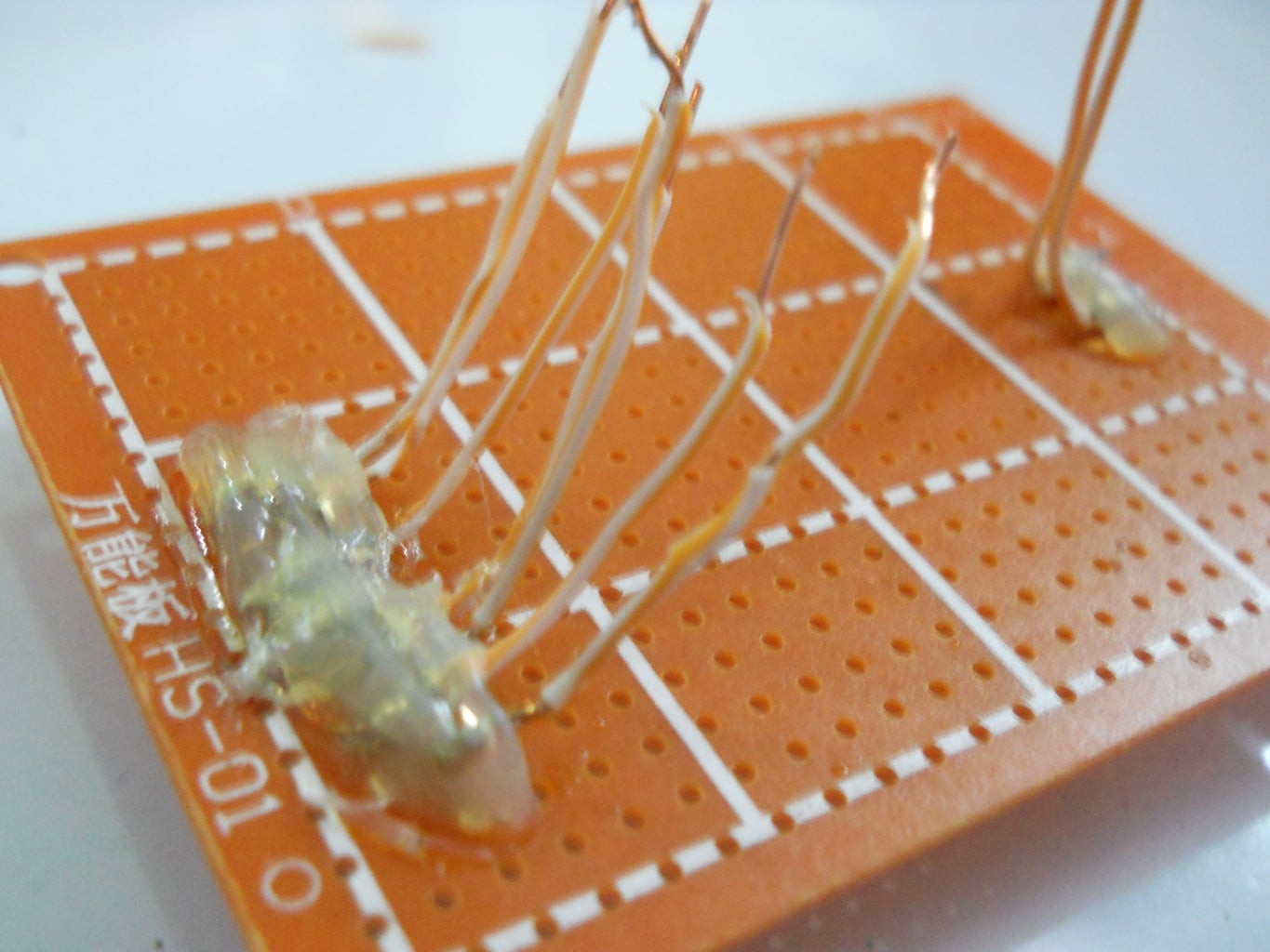
Step 2: Prototype and Pinout
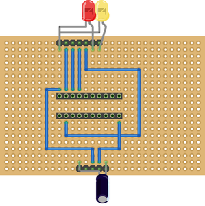
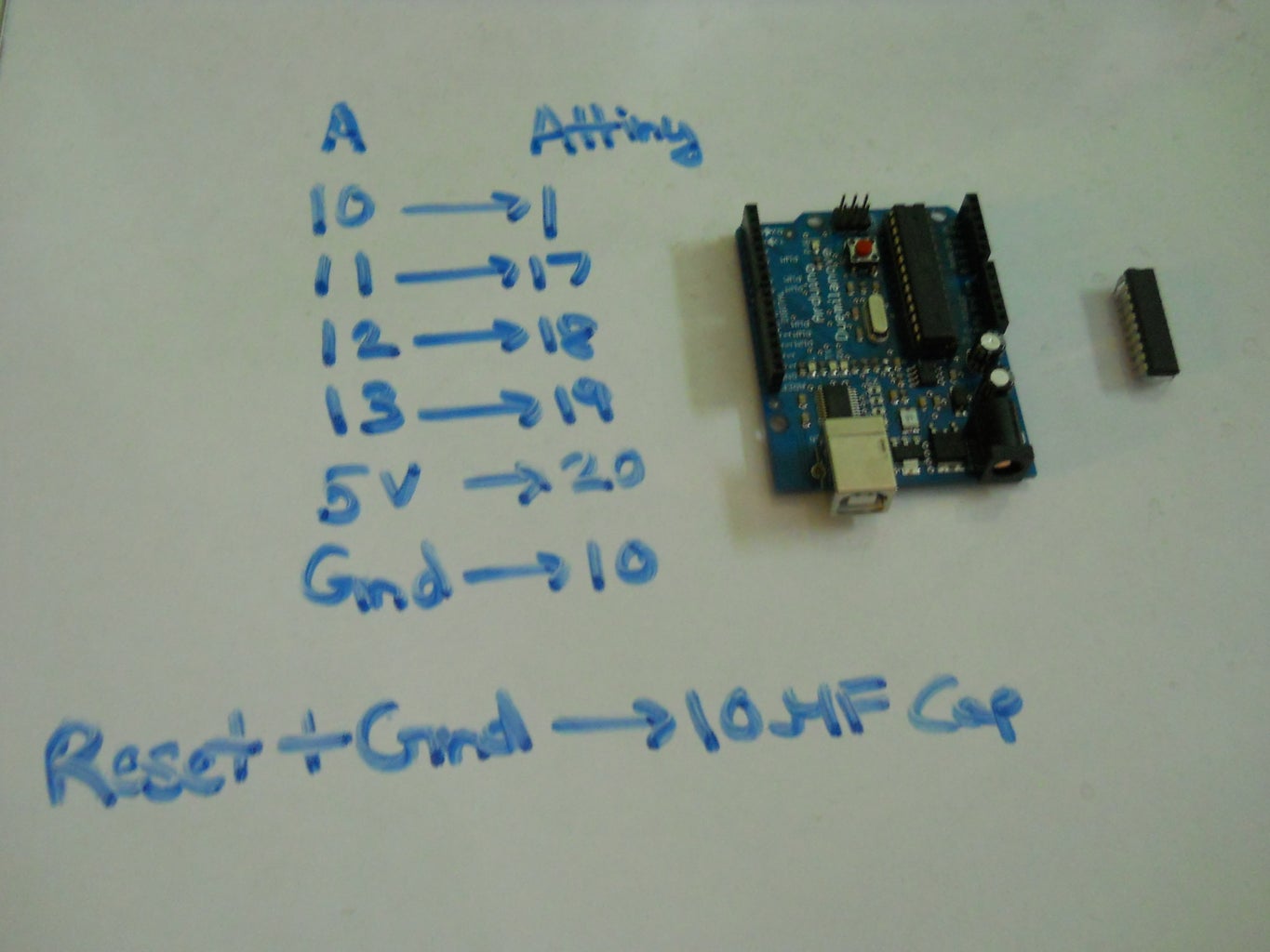
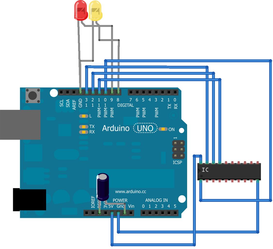
The image shows the pin-out diagram on how to wire up everything, you basically wire up everything as shown in the pin-out but not to the arduino directly but to a protoboard which has headers attached to them which can be attached to the arduino as a shield.
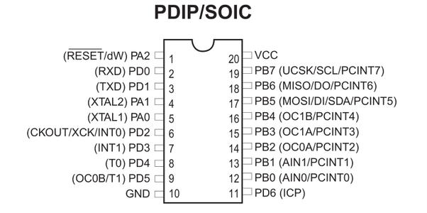
Make sure you keep the pin-out diagram of the ATtiny2313 next to you when wiring up everything to avoid any forgetful errors that may occur.
(Pin-out of ATtiny2313 Taken from http://blog.williambritt.com/uploads/attiny2313-pinout.png)
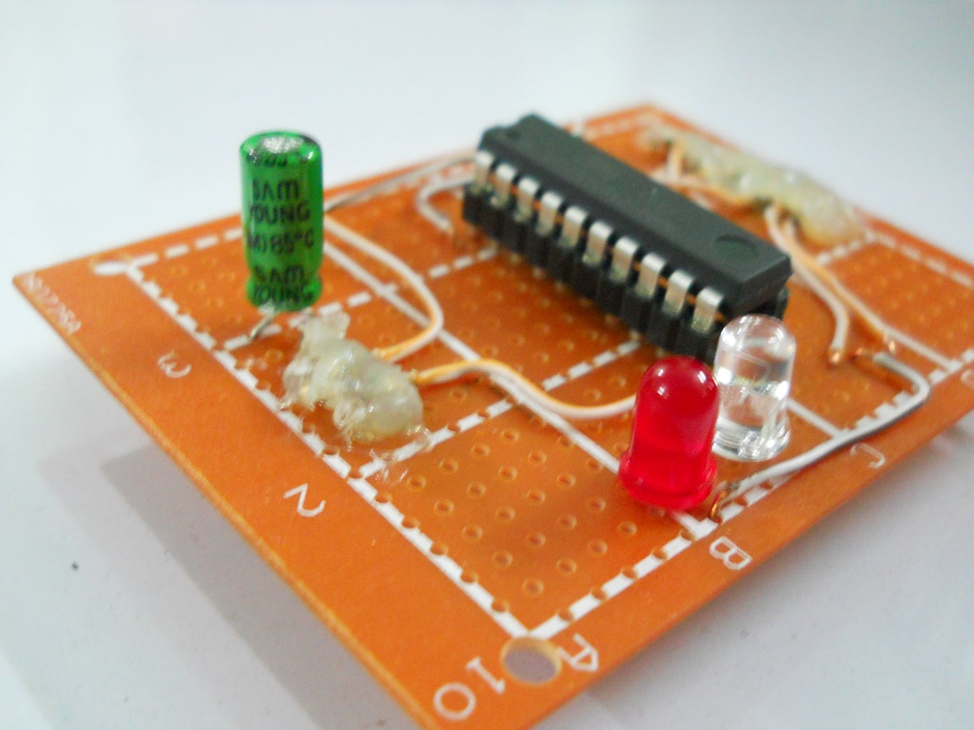
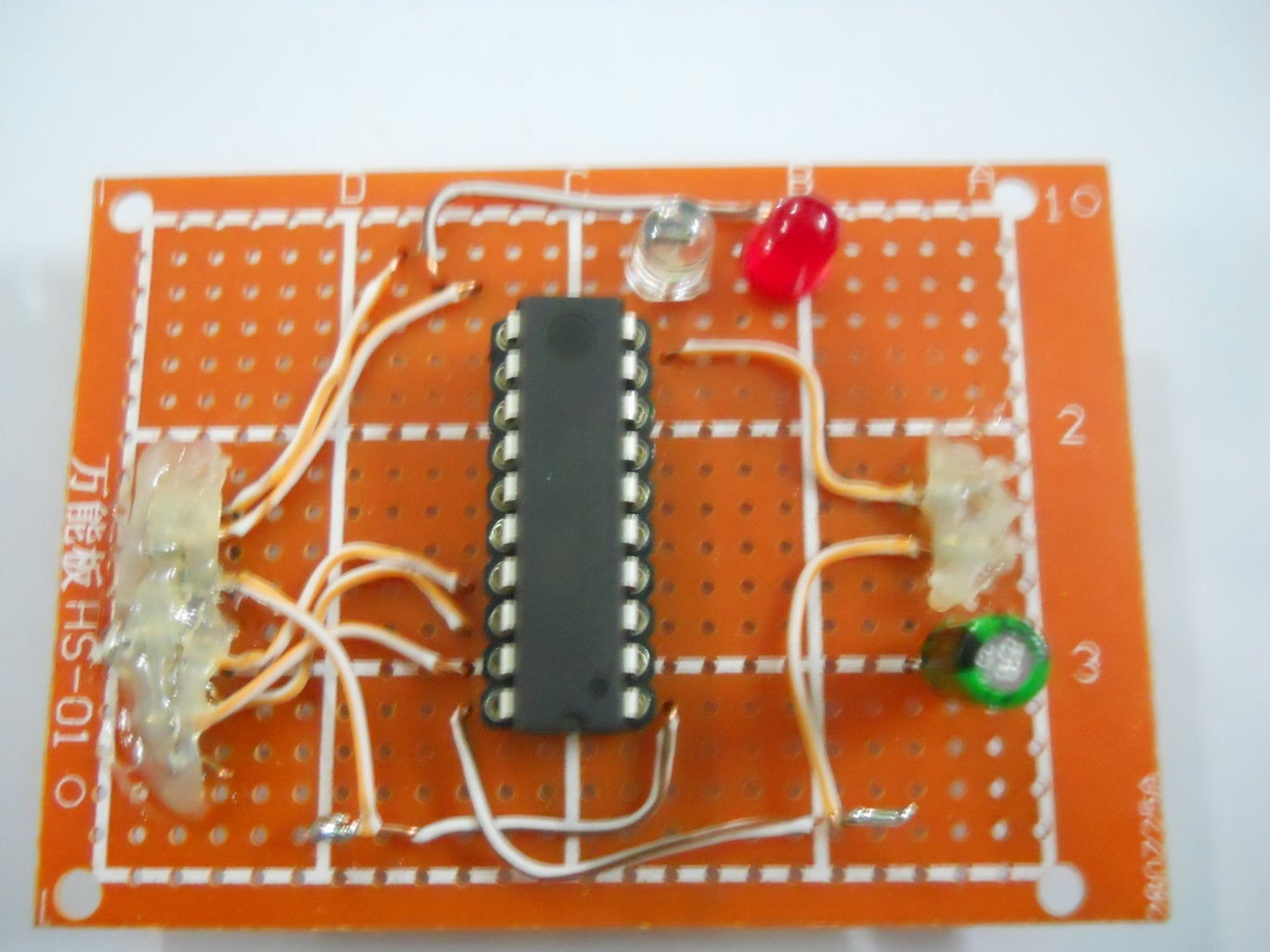
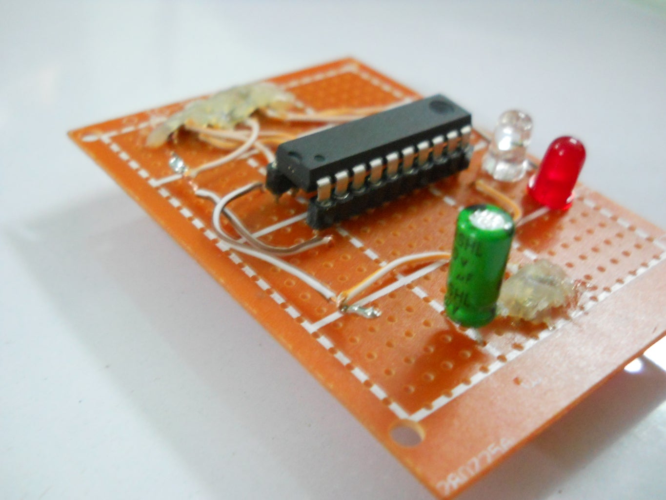
Step 3: Working on the Actual Shield
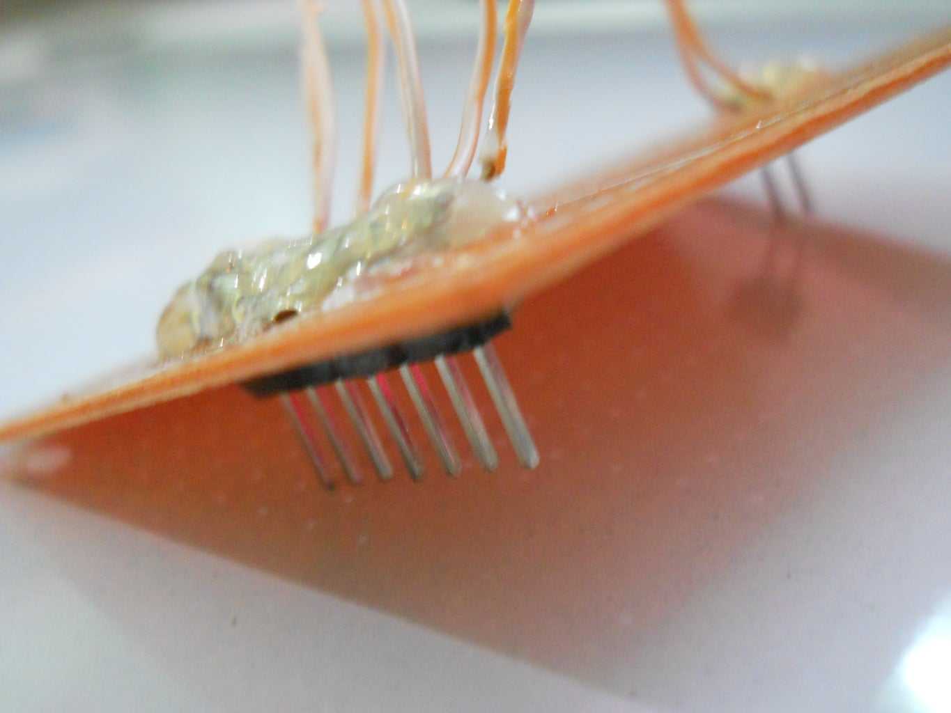
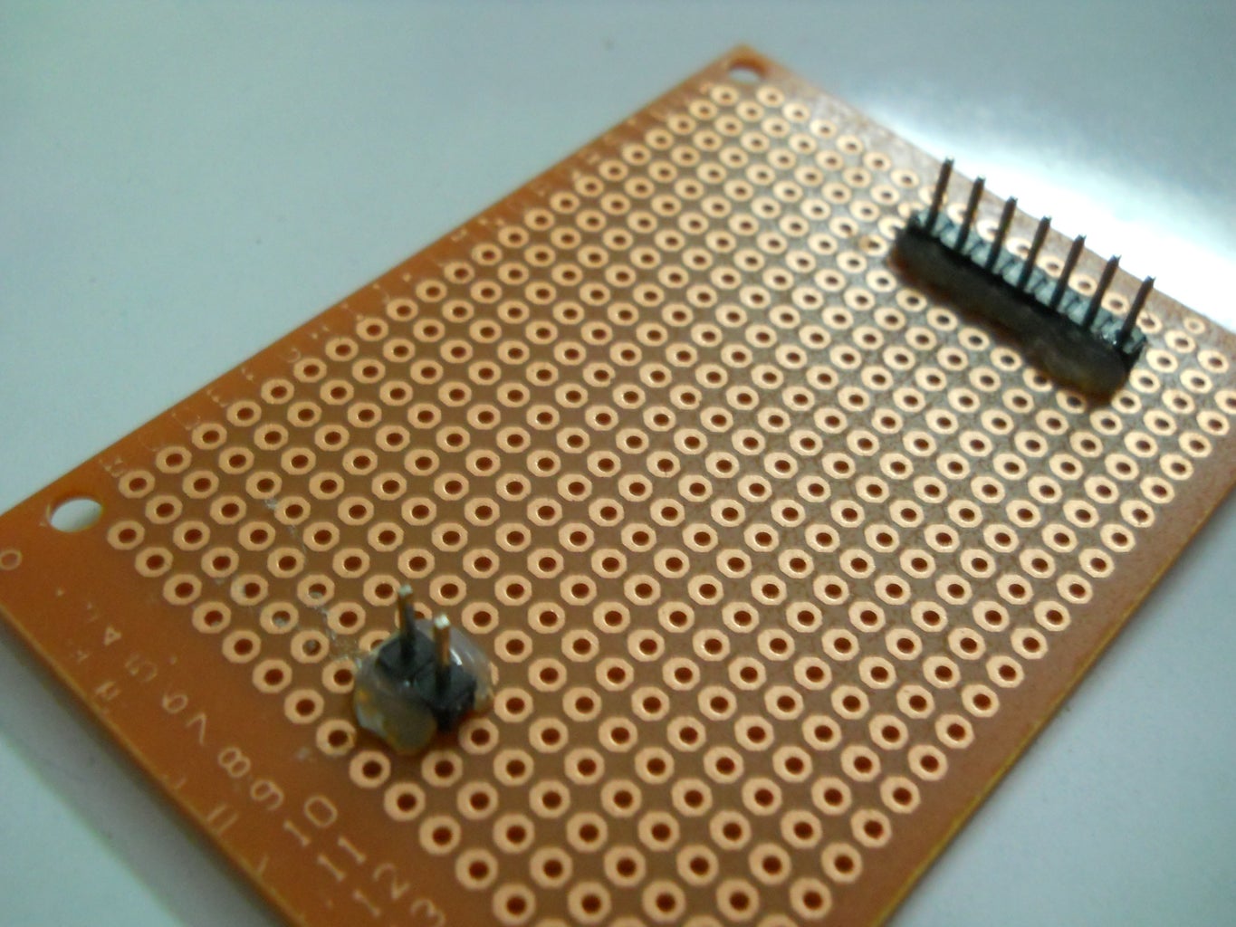


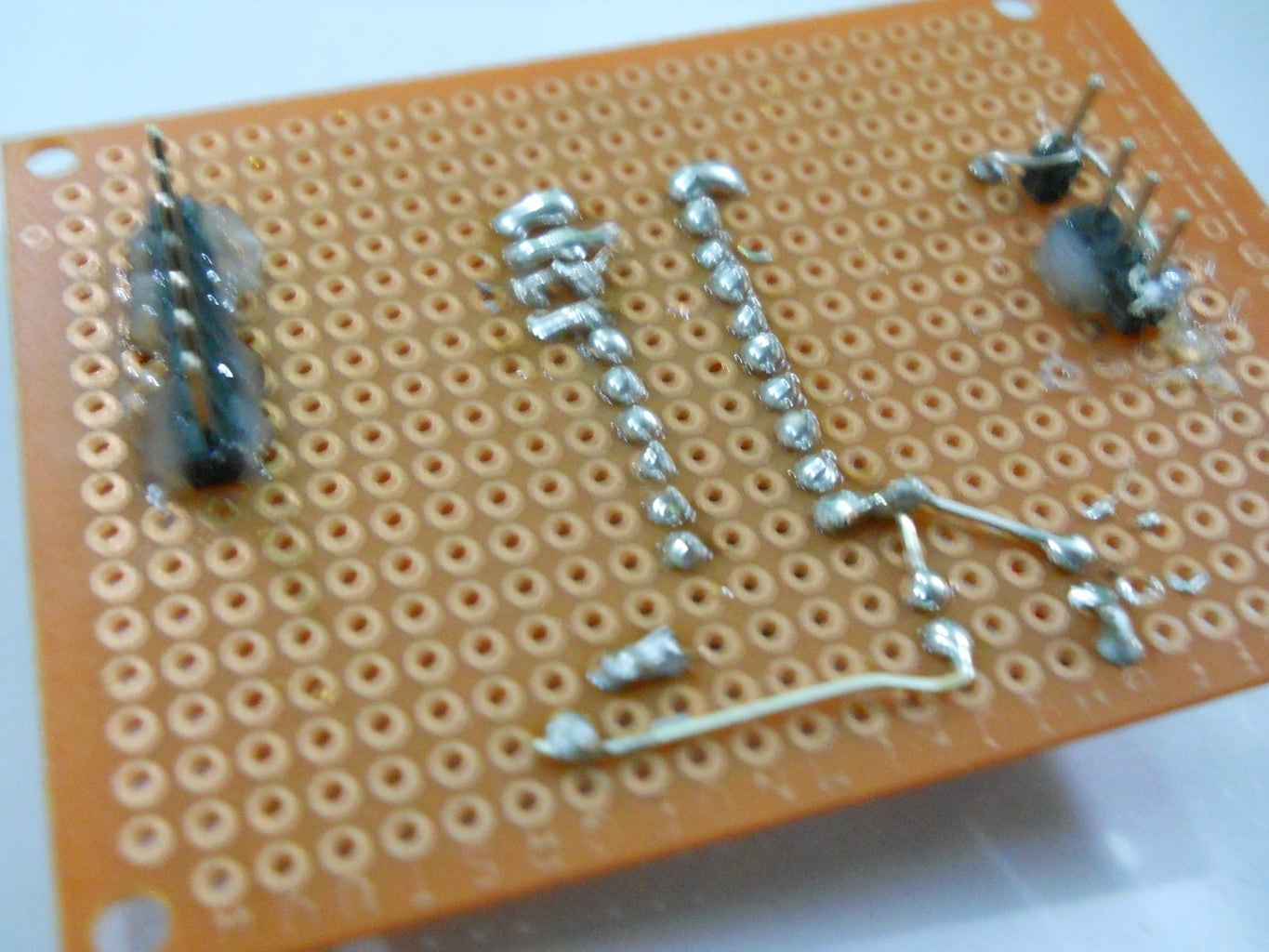
Start off by attaching the female headers in the center of the protoboard and then put the male headers in the arduino and then put the protoboard on it so as to get the exact position where to solder the male headers.
Then connect the right pins from the male header onto the female headers according to the pin-out (Female headers are going to be used to attach the ATtiny2313 and male headers are going to be used to attach the shield to the arduino)
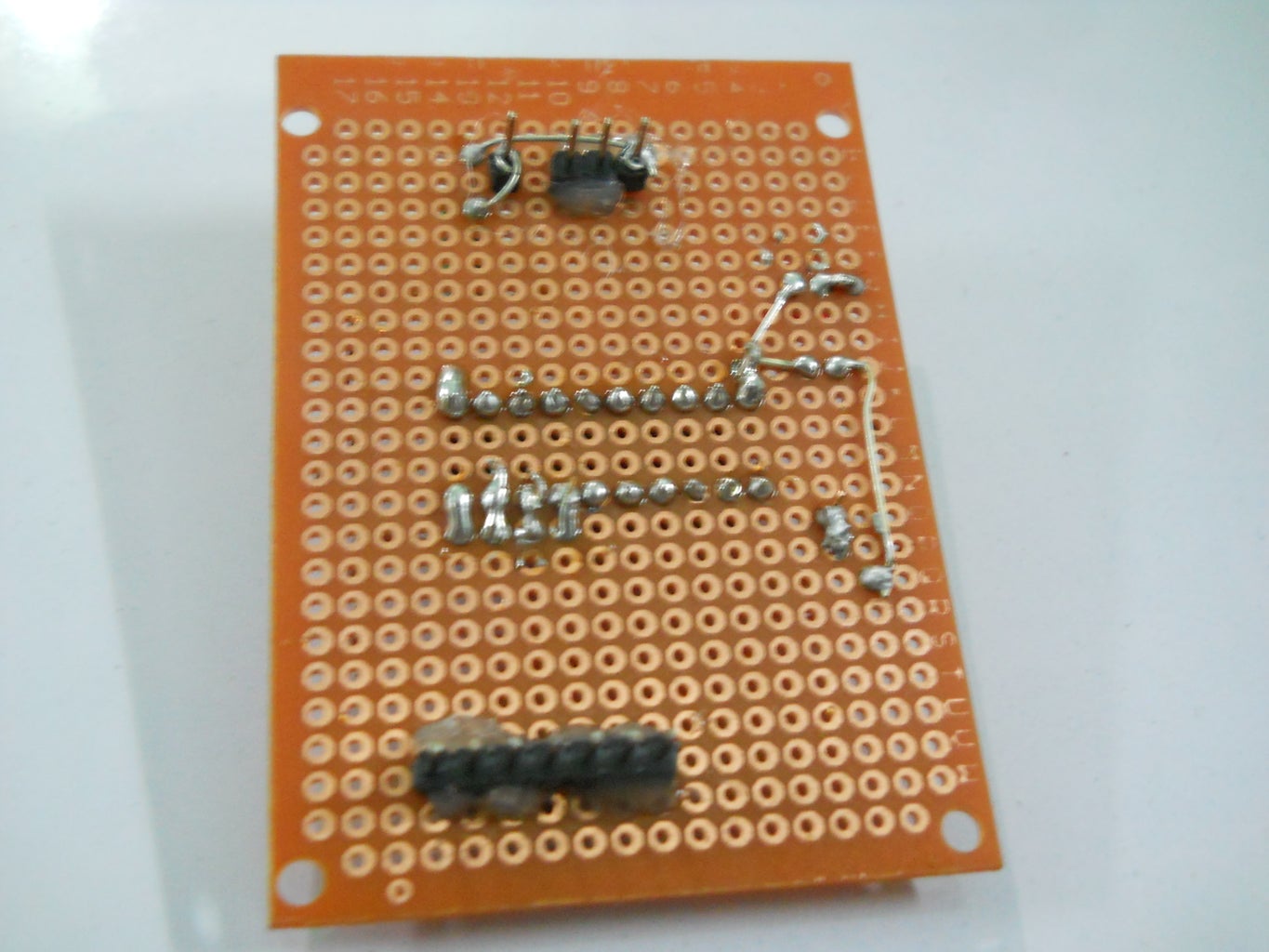
Then add the 2 LED's and the capacitor and connect them according to the pin-out as well, make sure the capacitor is attached the right way if its a polarized capacitor.
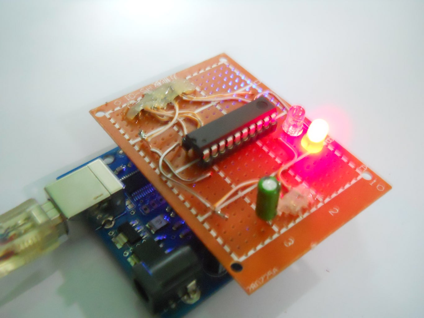
Then once everything has been wired up connect it to the arduino and upload a test code to make sure everything works fine (Instructions on how to do this on the next step), then once the testing is done you can add some hot-glue around the solder joints to make sure they are firm and don't make any sort of wrong connections. You could also use some electrical insulating gel/glue.
Step 4: Installing ATtiny Files
To program the ATtiny2313 there are 3 main steps;
1)Installing the ATtiny files
2)Setting up Arduino as an ISP
3)Connecting the shield and uploading the code
First download this;
http://code.google.com/p/arduino-tiny/
This download includes the files that need to be installed on the arduino IDE in order to program and use ATtiny boards with the Arduino programming environment.
By following the read-me, make sure that all the files are installed properly. As soon as they are installed, then when you go to Tools->Board, you should see a whole lot of new ATtiny options (There are ATtiny2313, ATtiny44, ATtiny84 and some ATtiny85 options).
Step 5: Setting Up Arduino As ISP

To set the Arduino as an ISP, first connect your arduino to the computer and open the example sketch 'ArduinoISP' by going to file, examples and ArduinoISP.
Then upload the code to the arduino by selecting the right board and right serial port in the options.
To make sure that you have uploaded the right program, in the next step you will make sure that the "Heartbeat" LED is working as it should (Fading on and off).
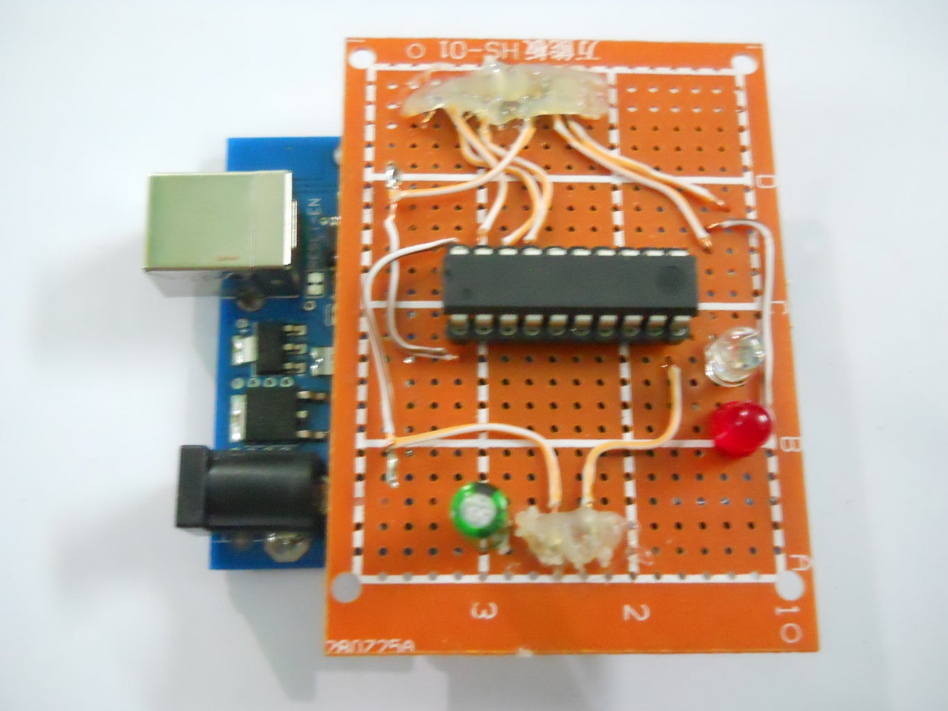
Step 6: Connecting the Shield and Uploading the Code
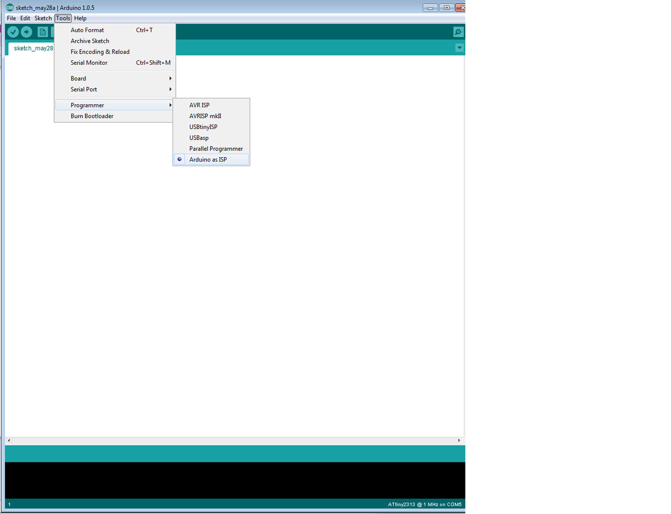

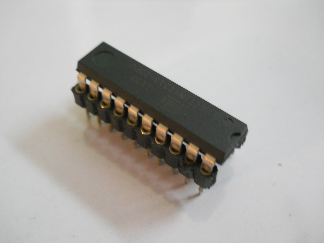
Now once that is done, connect the shield to the arduino and you should see the Heart LED fading at a regular interval. Now once you see the the LED is doing what its supposed to do, then attach the ATtiny2313 to the shield. Now go into the arduino IDE again and then go to Tools->Programmer and select Arduino as ISP.
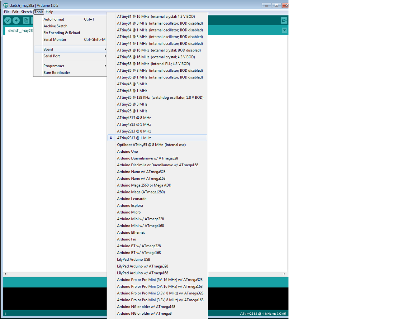
Then in the Tools->Boards, select the ATtiny2313 1Hz (Factory default sets the clock of the ATtiny2313 to 1Hz)
After selecting those 2 options then just open up your code and then hit Upload to upload the code to the ATtiny2313 with the Arduino as an ISP (Simply put, you are programming the ATtiny2313 by using the Arduino to connect it to the computer)
Once you are done uploading the code, then make sure you change the 2 options you changed back to the original so that you can upload code to the arduino again after doing this.
Step 7: What Next?


So now since you can program and use an ATtiny2313, why not try use these for all your future projects instead of Arduino's?
They are a lot cheaper than the Arduino (by 22-30 dollars) and they are capable of 18 I/O pins and they work with most of the common Arduino coding environment functions. The size of them is much smaller compared to the arduino as well which is very handy when trying to put things into small enclosures etc.
The only drawback of the ATtiny2313 is that some functions are not supported by it, so projects involving them cannot be done and the amount of I/O pins are limited.
But on the bright side, for small/simple projects these are great!
If you make any projects based on the ATtiny2313 or if you make this programmer, then be sure to upload a picture or a video of it and post a comment below :)

Second Prize in the
Kit Contest

Third Prize in the
Pocket Sized Electronics

Participated in the
Epilog Challenge V


