

Introduction: Arduino Auto Knock


This is not a cheap version of the $20 commercial motion sensor chime, nor a fancy one. I built this because I have the parts on hand, I enjoy building it, and I learn how to control ultrasonic sensor, relay module and solenoid with Arduino.
My office is free to enter for almost any workers, because I keep the tools in it. We also keep mineral water by the door, so regular customers just open my door and grab the cups of water. Well, sometimes we are just too busy to get them so we tell them to take by themselves.
When I am in my room, the door is at my back. You can say it is not good in Feng Shui way, but what can I say, this is the best position for me to get a better air circulation in this non air-conditioned room. And also this way I can see the front gate through my window. So let's say it is the door that is misplaced :D
I see that this solenoid can do the knock for me, to let me know when someone is entering my office and I can take a glance at the door before it is opened. Some uninvited will just shock with the knocking sound and decide to leave because they know that the room is under surveillance. I hope so...
Step 1: Parts to Grab
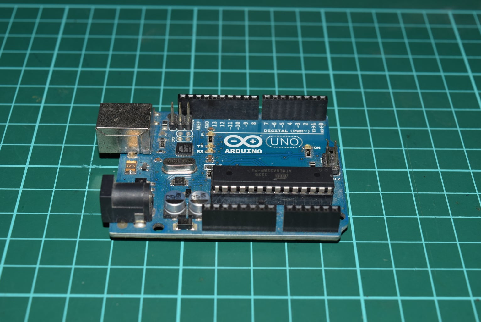


- Arduino Uno
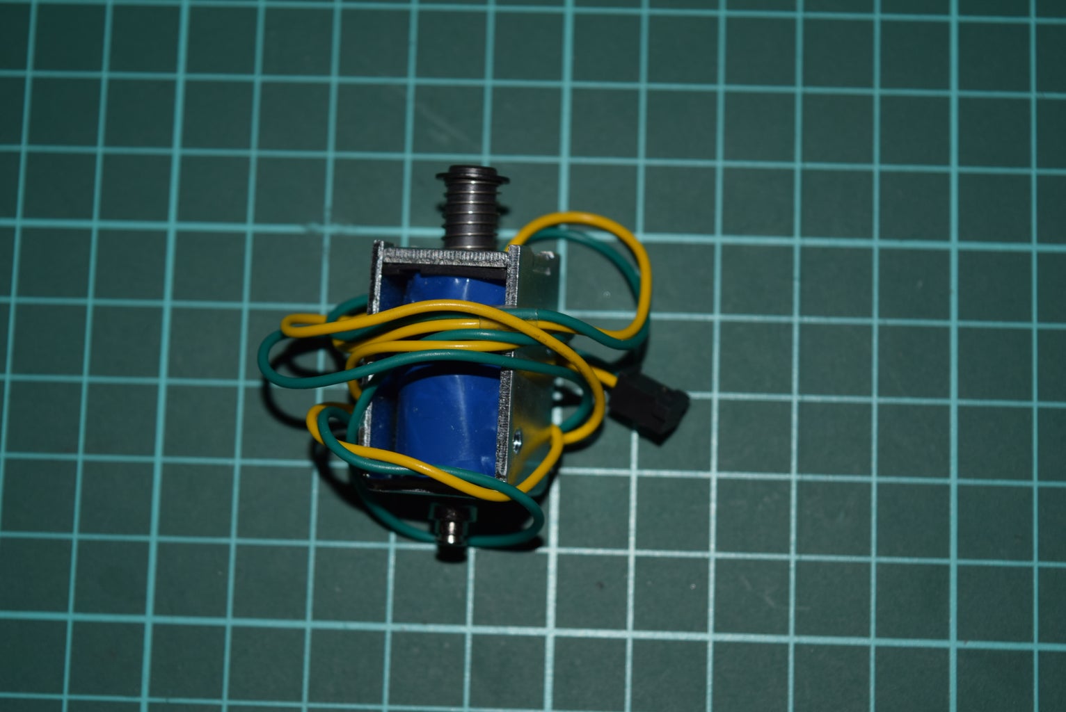
- 12V Solenoid
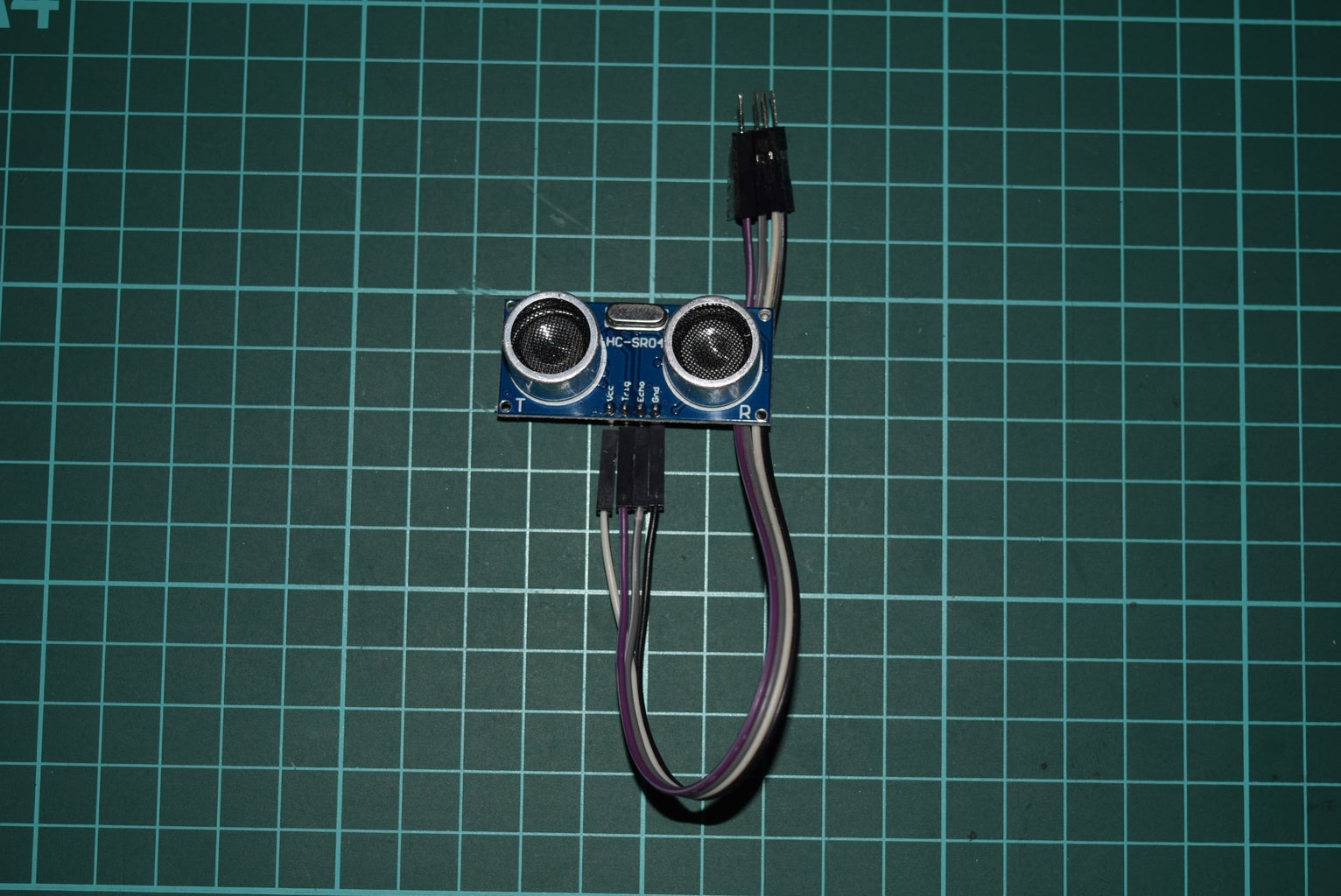
- HC-SR04 Ultrasonic Sensor
- 2 Relay Module, 5V
- Power plug with soldering PCB board
- 12V 2A adapter
- IN400x rectifier diode
- Mini breadboard (optional)
As I say, this is not a cheap version, but you can switch with any cheap parts to get the same result but with certain changes in wiring and code. Arduino Uno can be switched to any microprocessor you are familiar with. 12V solenoid can be switched to 5V version for simplycity, controlled directly from microprocessor without a relay module, but this is quite unsafe to the microprocessor because solenoid used to draw large current. You can simply use a 5-pin relay without the relay module. You can solder things directly and save a breadboard. This switching parts can make it cheaper than the commercial one for sure.
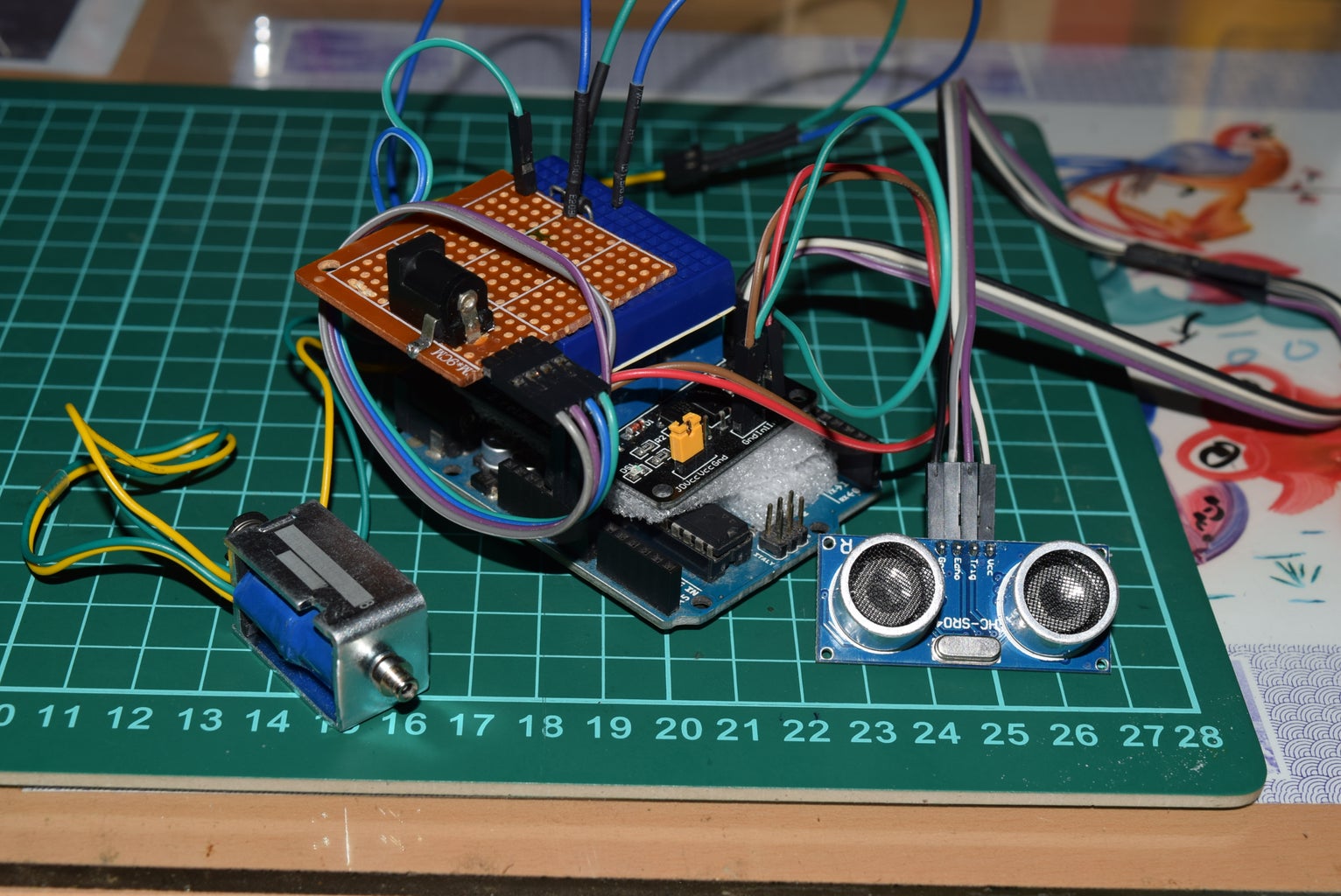
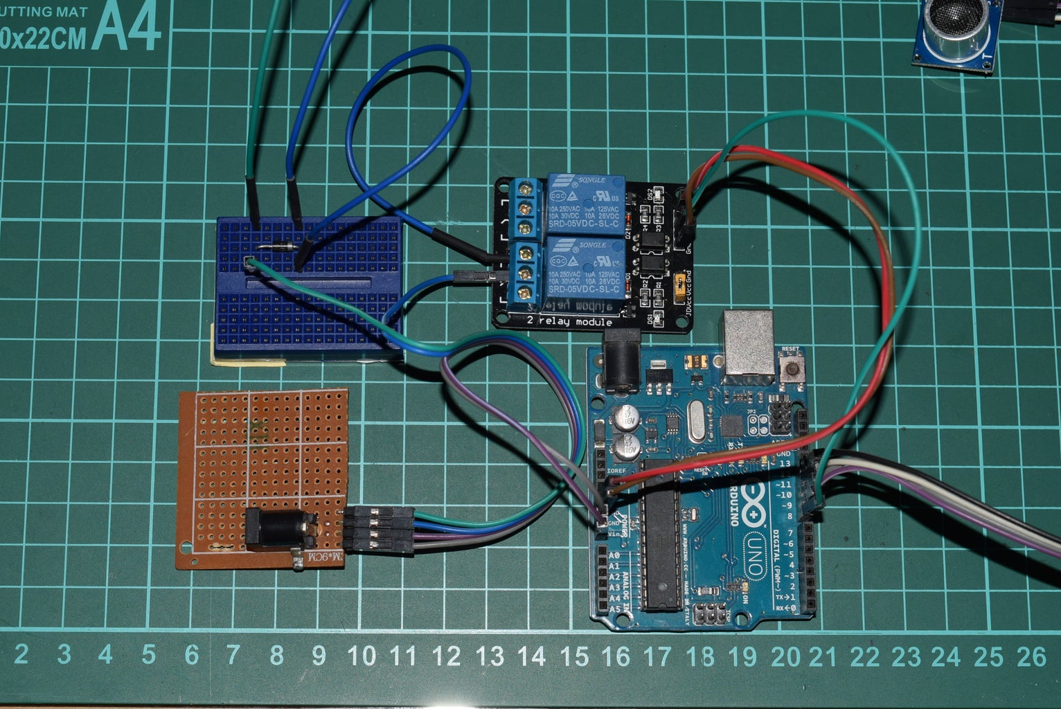
Step 2: Wiring Diagram

This is the complete wiring diagram and I will break it into several steps ahead.
Step 3: Wiring Ultrasonic Sensor to Arduino
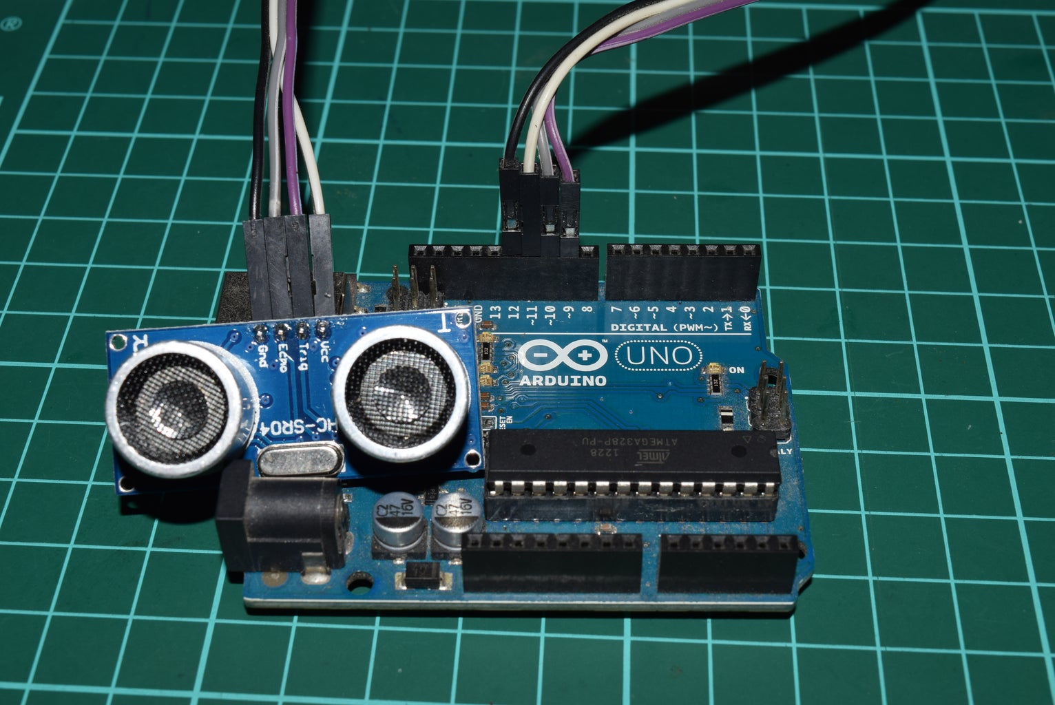
- Vcc to Arduino D11
- Trig(ger) to Arduino D9
- Echo to Arduino D10
- Gnd to Arduino D12
The length of wires depend on where you mount your unit (the whole bunch of electronics) and your sensor. Use any jumper wires for testing. When everything is working good, then you can adjust the wires and mounting and/or solder them all into a tiny rigid unit.
Step 4: Wiring Relay Module to Arduino
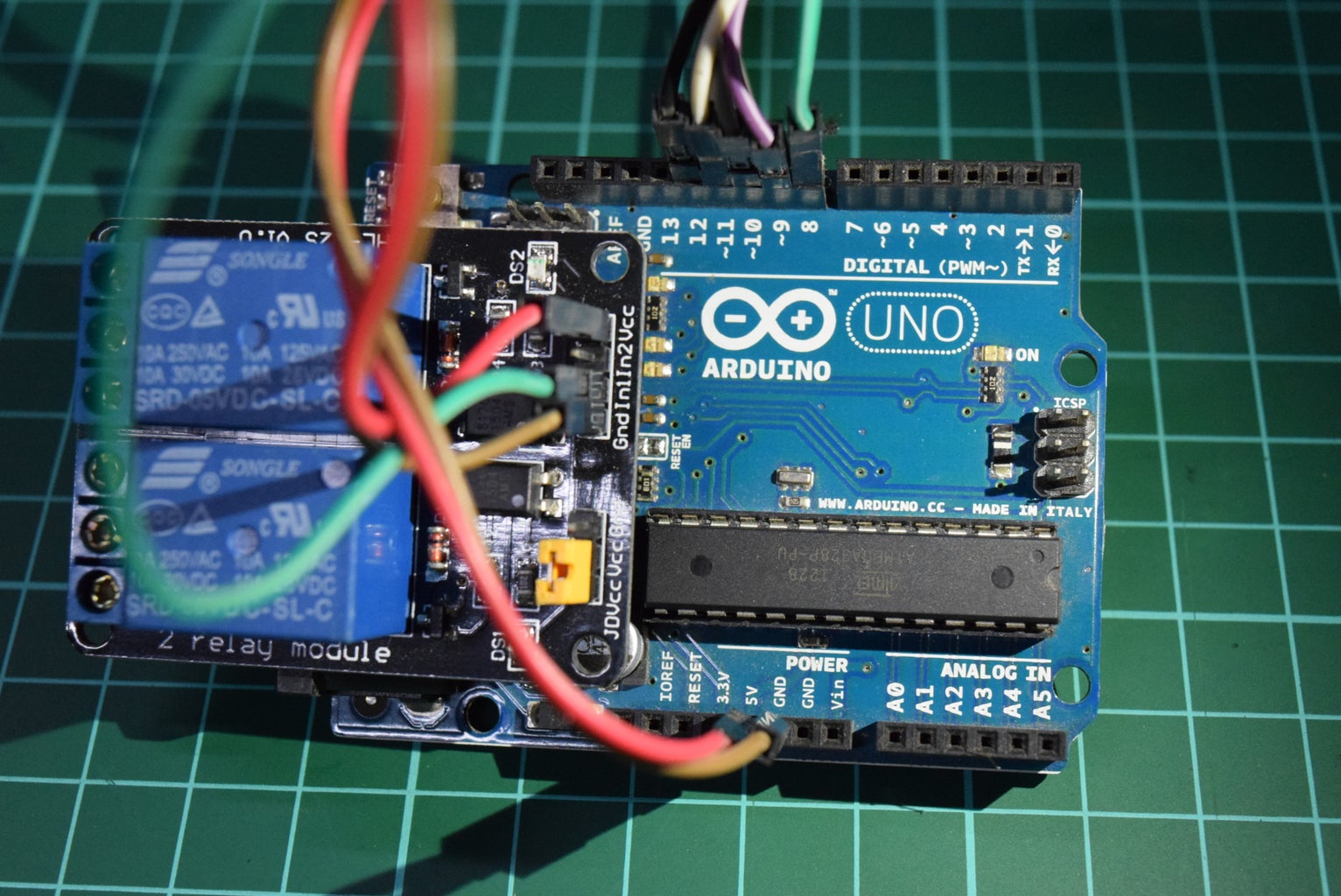
- Vcc to Arduino 5V
- Gnd to Arduino GND
- In1 to Arduino D8
If you decide to use a single 5-pin 5V relay without module board, then you need to adjust the wiring. Those pins are commonly labeled with : NO (Normally Open), NC (Normally Connected), COM (Common, usually in the middle, this pin connected to NC and will be switched to NO when the coil is energized), The other two beside the COM is called Coil Pins (connect both to Ground, when we give 5V to one of these pins then the relay will switch from NC to NO). I hope this simple explanation is clear enough for those who have just met relay switch :)
- Always put a rectifier diode (IN400x) between Coil Pins to prevent back EMF. For further information please click here or here.
- Connect one of the Coil Pins (where diode's grey bar is connected to) to Arduino D8.
- Connect the other Coil Pin to Arduino GND.
Step 5: Wiring the Solenoid

Solenoid wires have no polarity. There's no positive pin or negative pin. Simply connect both pins to a rectifier diode (IN400x) on a breadboard for testing. You can solder them directly and keep your breadboard once you are sure everything is working good. This rectifier diode has the same function as the previous one we put on a relay coil pins because solenoid is basically a coil, which create electromagnetic field to move the bar in the middle when it is given power through its pins.
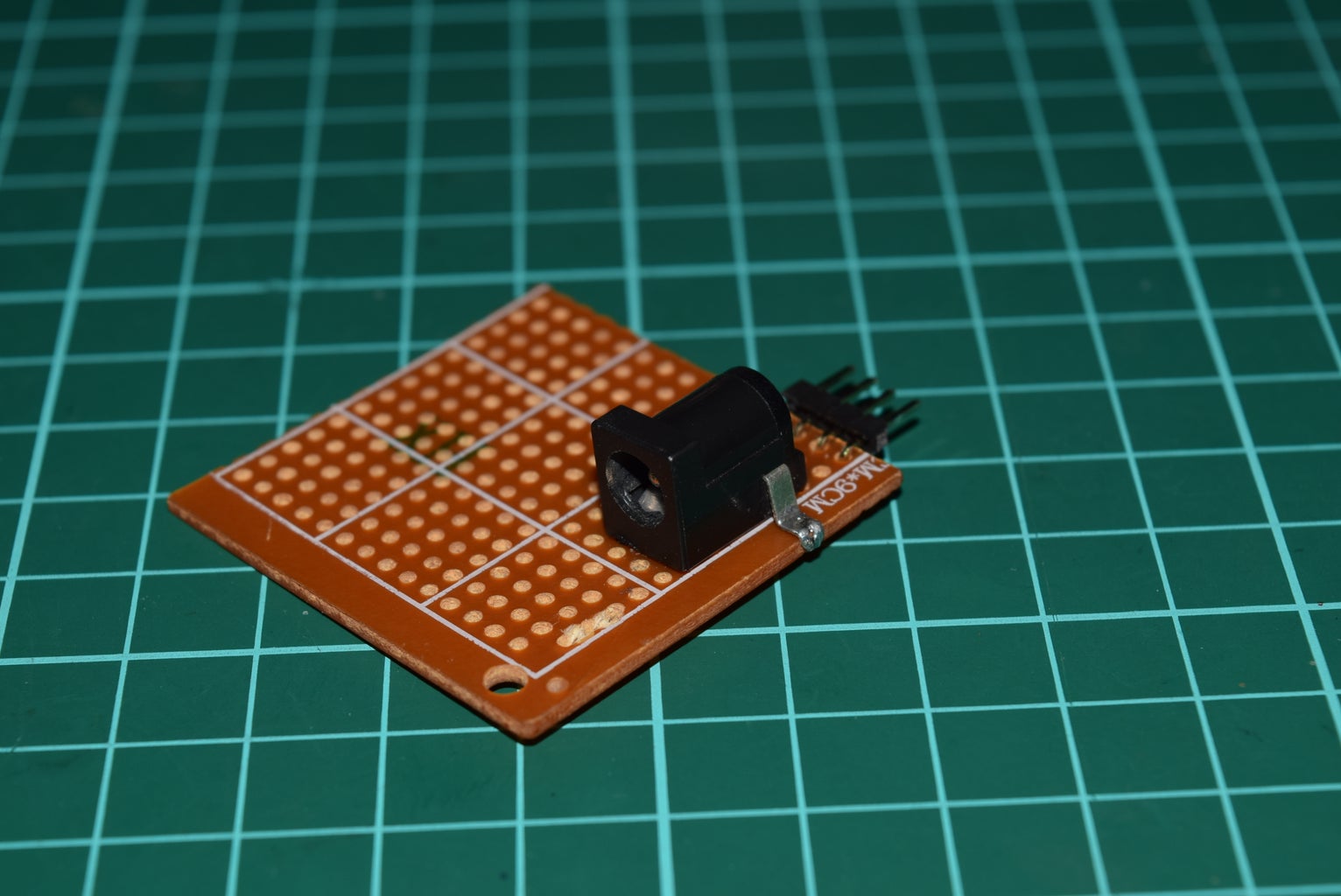
Step 6: Wiring the Power
Solenoid draws pretty much current. Even if you are using a 5V solenoid, you are not supposed to plug it directly into Arduino I/O pins because solenoid used to draw large current and will be risking your microprocessor. It is wise to put them on separate power. That's why we need a relay to switch the power on/off. I am using a 12V solenoid and Arduino Uno can be feed with 12V power. I simply make a power distribution on a small soldering board, from a DC barrel power connector with the output of two 12V pins (in the middle) and two GND pins (outer) and power them with a 12V wall adapter power supply.
- Connect one GND to solenoid (one pin far from the diode's grey bar).
- Connect one 12V to relay COM pin (the middle pin of relay).
- Connect relay NO pin to solenoid pin at the diode's grey bar. NO and NC on relay module board are labeled with diagram more or less like this : [ \ ] -- the left one is NC pin because the middle one get close to it, meaning the middle terminal will connected to this one when no power going to the coil. Then the right terminal is NO pin and will be connected only when relay's coil is powered.
- Connect the other 12V to Arduino Vin.
- Connect the other GND to Arduino GND.
We are done with the wiring session. Let's get to the code/sketch.
Step 7: Arduino Sketch

Copy and paste this sketch into your Arduino IDE and upload to your Arduino.
/* Arduino Auto Knock
 * using Ultrasonic Sensor HC-SR04, relay module, and solenoid
 * by Chienline @2017
 */

//defines pins numbers
const int knockPin = 8;
const int trigPin = 9;
const int echoPin = 10;
const int ultraVccPin = 11;
const int ultraGndPin = 12;
const int ledPin = 13;

// defines variables
long duration;
int distance;

void setup() {
  pinMode(knockPin, OUTPUT); // Sets the knockPin as an Output
  pinMode(trigPin, OUTPUT); // Sets the trigPin as an Output
  pinMode(echoPin, INPUT); // Sets the echoPin as an Input
  pinMode(ledPin, OUTPUT); // Sets the ledPin as an Output
  pinMode(ultraVccPin, OUTPUT); // Sets the ultraVccPin as an Output
  pinMode(ultraGndPin, OUTPUT); // Sets the ultraGndPin as an Output

  // input of the relay module works inversely
  // so a logic LOW at the input will actually active the relay and vice versa.
  digitalWrite(knockPin, HIGH); // Initially set the knockPin off.
  digitalWrite(ledPin, LOW); // Initally turn off the LED.
  digitalWrite(ultraVccPin, HIGH); // Sets 5V pin to power HC-SR04
  digitalWrite(ultraGndPin, LOW); // Sets GND pin to power HC-SR04
//  Serial.begin(9600); // Starts the serial communication
}

void loop() {
  // Clears the trigPin
  digitalWrite(trigPin, LOW);
  delayMicroseconds(2);

  // Sets the trigPin on HIGH state for 10 micro seconds
  digitalWrite(trigPin, HIGH);
  delayMicroseconds(10);
  digitalWrite(trigPin, LOW);

  // Reads the echoPin, returns the sound wave travel time in microseconds
  duration = pulseIn(echoPin, HIGH);

  // Calculating the distance into centimeter
  distance= duration*0.034/2;

  //if distance <= 90 cm then turn on ledPin and activate door knock;
  if (distance <= 90){
    knockTheDoor();
  }else{
    digitalWrite(ledPin, LOW);
  }

  // Prints the distance on the Serial Monitor
  //Serial.print("Distance: ");
  //Serial.println(distance);
  //delay(500);
}

void knockTheDoor(){
  int i;
  for(i=0; i<3; i++){
    digitalWrite(knockPin, LOW);
    digitalWrite(ledPin, HIGH);
    delay(150);
    digitalWrite(knockPin, HIGH);
    digitalWrite(ledPin, LOW);
    delay(150);
  }
  digitalWrite(ledPin, HIGH);
  delay(5000); //delay before the next sensor reading.
}
Step 8: Box 'Em All


We are done. Get all of them into a box. There I use an extension cord to reach a plug. So coming out from the box are :
- power cable
- selenoid
- ultrasonic sensor
My room has plywood walls with hollow inside, so I placed the solenoid on the glass window above the door, knocking the hollow wall. I put everything in a box. I taped the solenoid on top of the box. I ran the ultrasonic sensor wires through a small gap above my door to the front side. If you have no gap on your door, then you should find a way to mount everything outside your door, or run long wires to get the sensor outside. You can also put everything by the window with the sensor facing the door and adjust the triggering distance in the sketch.
The solenoid core (also called plunger or armature) has a light compression spring to pull the core at one side when it is not energized. I put this spring side facing the wall with the spring pressed a little against the wall. When we power the solenoid, the core will be pulled away from the wall, the spring is fully pressed. It is when the solenoid losing power, the core will knock on the wall. If you put it the other way, the solenoid core will push hard enough to the wall causing the whole unit (box) being pushed away. Then after several knocks, the core will not reach the wall no more.
Step 9: Mount and Plug

Mount the ultrasonic sensor (HC-SR04) in front of your aiming at the person coming though. In my case, there is a desk at the right side of my door. So I aim the sensor around 45 degrees downward and a little bit to the left (wall). This way it won't trigger the knock if I walk to the desk, but It will knock if I walk to the door. Half a meter from the door, that is when I try to reach the handle. This can be adjusted in the code according to the position of your sensor and the distance you want it to trigger the knock. In the sketch I wrote 90 cm to trigger, because the sensor is facing 45 degrees down so it will see a person's belly or a kid's head half a meter from the door. Of course you can try and change the sketch according to the position of your sensor and the way you want it to trigger the knock.
You don't need to knock on my door, but always remember to knock at others' for you don't know who/what is waiting behind the door ... [spooky sound's playing.]
I was thinking about turning on the fan (pointing to the door) so the comer get a "woooshh.." and/or playing some spooky sound for the next Halloween :D

Participated in the
Microcontroller Contest 2017

Participated in the
Sensors Contest 2017


