

Introduction: Arduino Binary Clock (hours, Minutes and Seconds)
Hello everyone; I was looking for this project for a long time. Finally I it it together with a lot of effort. For this project you will need:
1- Arduino Uno ($30 from Radio Shack)
2- RTC DS1307 (like $2 from EBay)
3- 2 Shift Registers 74HC595 (like $1 eachh from Ebay)
4- 16 leds
5- 16 330 hom resistors
6- Breadboards
7- jumpers
The clock will display the hours using the first 4 leds, then the minutes using the next 6 leds and finally the seconds using the las 6 leds.
There is a better explanation from the original project here (as well as other cool projects): http://www.multiwingspan.co.uk/arduino.php?page=bclock
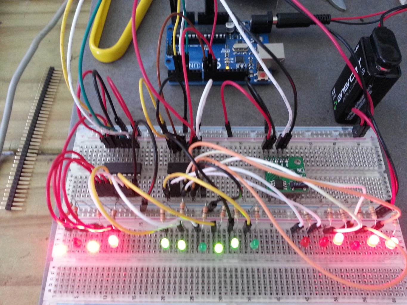
Step 1: The Schematics

Here is the design; mounted in two full breadboards! (Make sure you've got all the connections right, fail to to so will give you a few days of headache; it happened to me!)
Step 2: The Code (from Http://www.multiwingspan.co.uk by M Atkinson)
//orignal code made by M Atkinson, please check his website http://www.multiwingspan.co.uk
//few minor modifications made by cronos_80@hotmail.com
#include <Wire.h>
#include "RTClib.h"
RTC_DS1307 RTC;
int datapin = 2;
int clockpin = 3;
int latchpin = 4;
int datapin2 = 8;
int clockpin2 = 9;
int latchpin2= 10;
void setup()
{
Serial.begin(57600);
Wire.begin();
RTC.begin();
if (! RTC.isrunning()) {
Serial.println("RTC is NOT running!");
// following line sets the RTC to the date & time this sketch was compiled
//RTC.adjust(DateTime(__DATE__, __TIME__));
}
pinMode(datapin, OUTPUT);
pinMode(clockpin, OUTPUT);
pinMode(latchpin, OUTPUT);
pinMode(datapin2, OUTPUT);
pinMode(clockpin2, OUTPUT);
pinMode(latchpin2, OUTPUT);
}
void loop()
{
DateTime now = RTC.now();
// All used for checking the time of the clock
// This section can be removed when everything is working
Serial.print(now.hour(), DEC);
Serial.print(':');
Serial.print(now.minute(), DEC);
Serial.print(':');
Serial.print(now.second(), DEC);
Serial.println();
// End of section that can be removed
int mins = now.minute();
int secs = now.second();
int hr = now.hour();
// convert to 12 hour time
if (hr>12)
{
hr = hr-12;
}
// variables to describe pattern of on lights
byte data1 = 0;
byte data2 = 0;
// encode the time
// hr = 1st four bits controlled by the first shift register
for (int i =0;i<4;i++)
{
if (bitRead(hr,i)==1)
{
bitWrite(data1,3-i,1);
}
}
// mins on the first shift register (last 4 leds)
for (int i =2;i<6;i++)
{
if (bitRead(mins,i)==1)
{
bitWrite(data1,9-i,1);
}
}
// mins on the second shift register (first 2 leds)
for (int i =0;i<2;i++)
{
if (bitRead(mins,i)==1)
{
bitWrite(data2,1-i,1);
}
}
// seconds, controlled by the second shift register (all 6 leds)
for (int i =2;i<8;i++)
{
if (bitRead(secs,i-2)==1)
{
bitWrite(data2,9-i,1);
}
}
// output the information
writeByte(data1,1);
writeByte(data2,2);
// a pause every one second for the serial monitor output
delay(1000);
}
void writeByte(byte data, byte set)
{
int d,c,l;
if (set==1)
{
d = 2;
c = 3;
l = 4;
}
else if (set==2)
{
d = 8;
c = 9;
l = 10;
}
shiftOut(d, c, MSBFIRST, data);
// toggle the latch pin so that the data appears as an output
digitalWrite(l, HIGH);
digitalWrite(l, LOW);
}
Step 3: The RTClib
For this project you will need the RTClib in order to run the program properly. You can download it here:
http://arduino-info.wikispaces.com/DS1307_RealTime_Clock_Brick
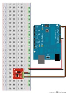
Your RTC will come loaded with the time; sometimes with local time from China; to change the time, go to this website http://bildr.org/2011/03/ds1307-arduino/, connect your RTC (the website will show you the diagram) and run the following code:
//Arduino 1.0+ Only
//Arduino 1.0+ Only
#include "Wire.h"
#define DS1307_ADDRESS 0x68
byte zero = 0x00; //workaround for issue #527
void setup(){
Wire.begin();
Serial.begin(9600);
setDateTime(); //MUST CONFIGURE IN FUNCTION
}
void loop(){
printDate();
delay(1000);
}
void setDateTime(){
//edit here the date and time
byte second = 20; //0-59
byte minute = 27; //0-59
byte hour = 22; //0-23
byte weekDay = 26; //1-7
byte monthDay = 22; //1-31
byte month = 11; //1-12
byte year = 13; //0-99
Wire.beginTransmission(DS1307_ADDRESS);
Wire.write(zero); //stop Oscillator
Wire.write(decToBcd(second));
Wire.write(decToBcd(minute));
Wire.write(decToBcd(hour));
Wire.write(decToBcd(weekDay));
Wire.write(decToBcd(monthDay));
Wire.write(decToBcd(month));
Wire.write(decToBcd(year));
Wire.write(zero); //start
Wire.endTransmission();
}
byte decToBcd(byte val){
// Convert normal decimal numbers to binary coded decimal
return ( (val/10*16) + (val%10) );
}
byte bcdToDec(byte val) {
// Convert binary coded decimal to normal decimal numbers
return ( (val/16*10) + (val%16) );
}
void printDate(){
// Reset the register pointer
Wire.beginTransmission(DS1307_ADDRESS);
Wire.write(zero);
Wire.endTransmission();
Wire.requestFrom(DS1307_ADDRESS, 7);
int second = bcdToDec(Wire.read());
int minute = bcdToDec(Wire.read());
int hour = bcdToDec(Wire.read() & 0b111111); //24 hour time
int weekDay = bcdToDec(Wire.read()); //0-6 -> sunday - Saturday
int monthDay = bcdToDec(Wire.read());
int month = bcdToDec(Wire.read());
int year = bcdToDec(Wire.read());
//print the date EG 3/1/11 23:59:59
Serial.print(month);
Serial.print("/");
Serial.print(monthDay);
Serial.print("/");
Serial.print(year);
Serial.print(" ");
Serial.print(hour);
Serial.print(":");
Serial.print(minute);
Serial.print(":");
Serial.println(second);
}


