

Introduction: Arduino Bluetooth Part 2 - BT Communications


The objective in this part is to configure two Bluetooth modules and get them paired up.
After the first part we have a BT module connected up to an Arduino. The module has all its parameters as defaults except the module name. It will work just the same as a brand new module.
Close the Arduino IDE session on the PC if it is still running.
Step 1: Master Module Set Up
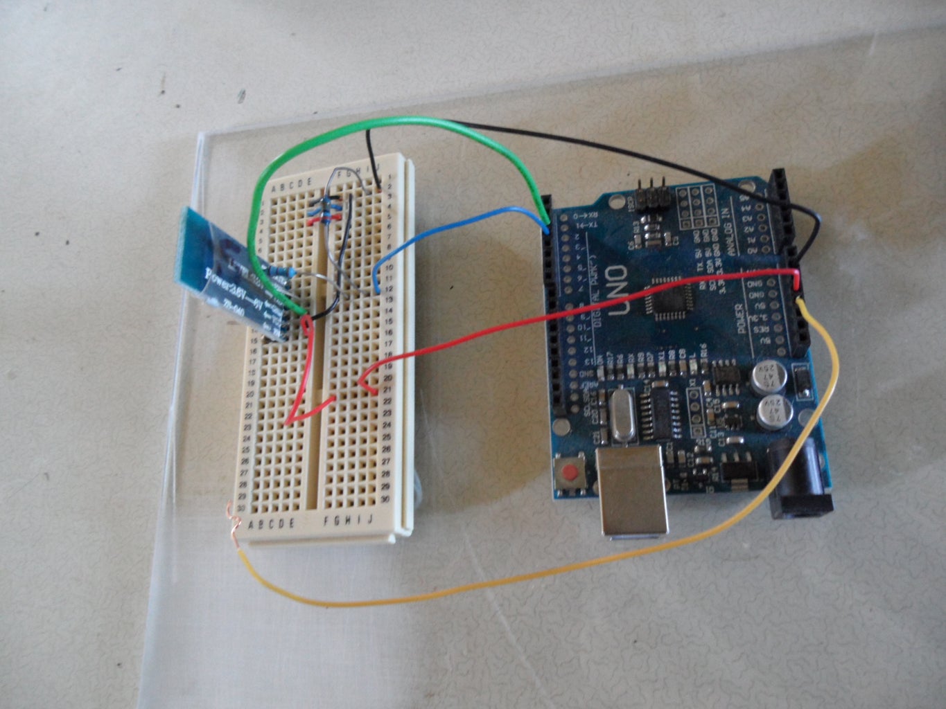
I set up another Arduino, this time a Uno, with another BT module wired up in the same way as the first one.
I need to make some changes to the settings in the new module so this will be a master and it will search for the slave module and pair with it.
I connected the USB cable from this module to a different USB connection on the PC. Now I have two Arduinos using different ports on my PC.
To avoid confusion, unplug the USB cable of the slave module for the moment.
Start up a new session of Arduino IDE.
Alter the Tools settings to show the correct board and the COM port.
Load the BT_config program into the Arduino.
Put the BT module into AT mode with the 3.3v wire.
Start the Serial Monitor and try the "AT" command.
If all is well the module will respond with "OK" and we are at the same point we had with the slave module.
Step 2: Master Module Configuration
To make the module a master I used this dialogue:
AT
OK
AT+ROLE=1
AT+CMODE=1
AT+NAME=MST01
AT+ROLE
+ROLE=1
AT+CMODE
+CMOD=1
AT+NAME
CMODE default is 0, "connect to any" which was good for the slave. The master has it set at value 1.
Step 3: Pairing the Modules
Cycle the power to the master BT module by removing the 5v supply and reconnecting it. The LED should be flashing rapidly.
Download and open the BT_talk2 program and load it into the Arduino. Open the Serial Monitor for the master module.
Plug the slave USB cable back in and start up another Arduino IDE session.
Open the BT_talk2 program, check the Arduino type and COM port are ok, then load the program into the Arduino that has the slave module.
Open the Serial Monitor for this session. There are now two Serial Monitors on the screen, one for each Arduino.
Have a look at the BT modules.
What should be happening is the master sees the slave module, the slave module is configured to connect to any master so the two modules should pair up.
On mine, the blink rate of both modules went to twice every two seconds. On other modules the slave may be continuously on.
Now anything typed in one serial monitor should appear in the other one. If that's happening we have two Arduinos connected via Bluetooth.
If you are getting a response but it's garbage, odds are that the speed setting somewhere is wrong.
The default speed for comms in the BT module is 9600. This can be checked in AT mode with
AT+UART
It can be set to the default with
AT+UART=9600,0,0
Attachments

Step 4: BT Default Comms

The BT_talk2 program is basically the same as BT_talk except that it sends data from the Serial Monitor to the BT module as well as reading from the BT module and sending to the Serial Monitor. So it's a two-way communication. The BT modules still talk to the Arduinos at the default comms speed of 9600.
When I type on the Serial Monitor and press enter, the line of data is sent to the Arduino which passes it through to the BT module. The BT module sends it to the paired module.
When the data line is received by the paired BT module it passes this to its Arduino which sends it up to the Serial Monitor. So the data travel between the Serial Monitors. It works in both directions.
When the slave module starts up it will connect to any master that finds it. Equally the master module will try to make a connection with any available slave module. If there a few other BT modules active in range (about 10M) they could hook up with the wrong one.
It would be very useful if this master and this slave would always connect with each other and not to any other device. That's what I will do next.
Step 5: Continuous Pin34 Connection

When the module is AT mode, some of the settings can only be changed if pin34 is high all the time. To make my modules permanently paired up I need to change some of these settings.
I can't hold the wire against the pin all the time so I have to make a more fixed connection. I could solder a wire to pin34 but I would be afraid of wrecking the module as my soldering skills are not brilliant. Also, the pin only needs to be high while we are configuring the module. Once that is done we don't need the connection any more.
I found that I could modify a thin-wire paper clip to slip over the module and have the end of the wire touching pin34. This should not harm the module as the force of the paper clip is very small and the module has a protective plastic cover as well.
Now to put the module into AT mode I can gently hook the 3.3v wire onto the paper clip and the pin stays high all the time.
Step 6: Modified Paper Clip

The paper clip slips over the module and the end has been bent around so that it touches pin34.
Step 7: Configuring the Permanent Pairing
To permanently link the two BT modules, the master has to be reconfigured.
Load the BTconfig program into the Arduino attached to the master.
Make the continuous pin34 connection and cycle the BT module power.
The LED on the module should flash once per two seconds.
Run the Serial Monitor and check that the "AT" command gets the "OK" response.
The slave module is still running but will revert to rapid flashing while it waits for a connection. Leave it running like that.
Now use the following dialogue to change the settings in the master BT module (my comments in italics):
AT+ORGL reset module defaults
AT+RMAAD clear any pairing in the module
AT+ROLE=1 set module as master
AT+RESET reset module
AT+CMODE=0 connect with any
AT+INQM=0,5,9 search for up to 5 devices, search for 9 seconds
AT+INIT if this command generates an error message, ignore the message and continue
AT+INQ start the device search
The BT module will search for other available devices for up to 9 seconds. Any found will be displayed.
The slave module should be found and its address displayed in the form 1234:56:789ABC,0,777F
The first 12 hex digits are the unique ID of the module found.
Note that commas are used instead of colons in the commands that follow. Put the address of your slave device in place of 1234,56,789ABC.
AT+RNAME?1234,56,789ABC show readable name of the device.
If the slave module was renamed "MOD01" earlier, this name should show up.
AT+PAIR=1234,56,789ABC,9 try to pair with this device for up to 9 seconds
AT+BIND=1234,56,789ABC
AT+CMODE=1
AT+LINK=1234,56,789ABC
Now the modules should be permanently linked together. Any time they are both powered up they will automatically pair up but won't connect to anything else.
Remove the wire from pin34 of the master module.
You can try pulling both USB cables then reconnecting the slave one. The slave module LED should flash rapidly while it waits for a connection. Now if you search for this module with you cellphone/tablet you should find it cannot connect. When the master module is powered up it should pair immediately with the slave.
Now we have two Arduino modules which can talk to each other using a wireless connection. This is the basis of remote control for all kinds of projects.


