

Introduction: Arduino Claw Machine


WHAT?
Machine is about 1:4 scale, perfect for candy and other small toys/prizes. Footprint is ~20x26x19 inches, made from aluminum extrusion, custom laser cut acrylic/wood, stepper motors (Nema17) and an Arduino Mega. Stepper motors move the gantry and a servo motor controls the claw (giving the claw an analog grip, not just open/close). Some parts are sourced from the plentiful DIY 3D printer market, other parts are custom 3D printed, and clever uses for "that's not what that thing is designed for" complete the functionality of the machine.
WHY IS IT SPECIAL?
The claw machine functions just like traditional claw machines in arcades, except my machine gives you more control and fairness. The game is based on a timer (there is an LCD indicating how much time is left) which is set to 55 seconds. Insert a quarter (can be set to free-play), and press start. You have 55 seconds to move and position the claw, grab a prize, return it to the "prize chute" and go for more. Once time runs out the claw closes, the gantry moves back to the 'home position' and the claw then opens dropping anything it might be carrying. Unlike the traditional Arcade claw machines, my DIY version gives you full control over this claw in the X,Y,Z axis and the claw grip itself. The only restriction is time. Personally, the game is more fun since it's based less on one-time spatial judgment and more about motor skills and planning the best route for multiple prizes.
FULL CONTROL?
Really early crane amusement machines were based on full control machines. Personally, I think they are incredibly fun not to mention charming in their ingenuity. The last photo is a fully restored Junkyard game from the 1960's as example. The goal is to load diecast 'junk' cars into a hopper. I was able to play this machine at a Coin-Op Museum in Hopewell PA. Awesome game
No part of my claw machine came from any 'kit'. Total time with building, wiring, designing (2D + 3D CAD, PCB layout) for both v1 and 2 machines is likely near 300 hours.
Step 1: Bill of Materials


Let me first say there are many ways to build this claw machine. I found that making a hybrid CNC/ 3D printer machine makes things simpler mechanically, as these parts are readily available, cheap, and more modular as they are marketed to build a variety of machines. You could definitely go the tradition claw machine route using DC motors for the gantry, which simplifies the power electronics (H bridge ICs) and code to drive them; however, the trade off is it complicates the drive mechanics. Most claw machines have worm gears that drive the gantry, giving the speed reduction and required torque. I prefer a 'bolt-on' approach rather than a custom fabricated mini version for the gantry. I found stepper motors are crazy easy to mount, have a good range in speed (on the low end of speed), and provide more torque than I need (think scalability), so this route was chosen.
COST TO BUILD:
I included a modified Bill of Materials for this machine. The BoM reflects the machine documented here. The total cost is $470. The crossed out items in the BoM reflect the reduced cost version. This removes all the Aluminum extrusion (in place of a wood frame) and some other non-necessities like the LCD and mechanical coin acceptor; reducing the cost to about $210.
I did not expect this machine to cost so much. On the bright side, with a quarter slot it can pay for itself over time and even become profitable. So let's call this build an 'investment'
WHERE TO BUY PARTS:
eBay. If you can wait for things to ship from China, you can't beat those ebay prices.
WHY DID YOU USE ____ PART?
I got the steppers from a USA eBay seller who sells refurb and rebuilt steppers (about $8 per stepper) and I must say the steppers are awesome. Each motor has a molex connector at the base making build/ disassemble simple. The Arduino Mega is a off-brand from DealExtreme (works just fine), and the Al extrusion came Misumi USA (cheaper than 80/20 brand). The cost is pretty high as I buy more than I need and prepare for mistakes (I killed a few ULN2803's and TIP120's already) . It might be better to build this from DC motors, but I went with Nema 17 steppers primarily for two reasons, Mounting them uses a standardized hole pattern, and building a controller for them might prove useful in later projects. This project is easier to replicate (think kit form) with standard parts- Nema Steppers fit this due to the 3D printer market, not to mention all the belts, pulleys and wheels are readily available 3D printer parts. I have saved a few $ by making my own claw, and brackets to form the XYZ gantry. I should stress designing and building the claw was a chore, but well worth it considering the alternatives I tried. I bought (then returned) a few claws as I was thoroughly disappointed in their quality. There are many parts out there for gantries (Inventables' Maker rail...etc) but building my own was cheaper and simpler as surprising as that sounds. I was loathing the task of replicating/ relying-on dimensioned parts from around the web in hopes that everything would "work", but soon gave up on that since just one error in any drawing propagates into frustration after you bought said parts and they just don't fit right. Things have been rather simple with the steppers as I have been sticking to 5mm bore. This 5mm seems to be the most common DIY 3D printer parts, which are everywhere on eBay for cheap.
TL:DR Cost=$470 using Al extrusion for frame, built from 3D printer parts and custom designs from scratch. Total cost is ~$210 if you build the frame from wood.
Step 2: Build Frame


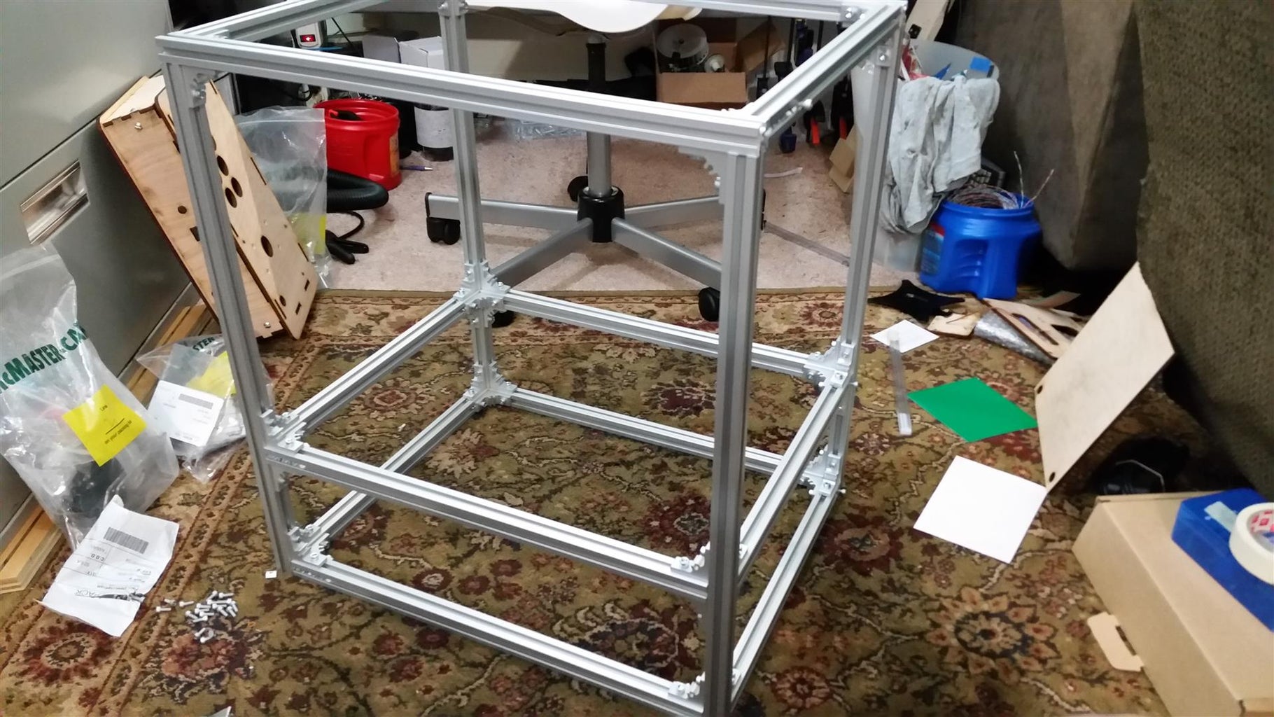

This is a AEX frame kit from MisumiUSA. Just specify the dimensions and you get everything pre-cut with all the hardware to build the frame. Sure it's a bit more costly, but the alternative was buying the raw extrusion in longer stock, cutting each one on the cold-saw, deburring each cut, cleaning the coolant off each cut, and messing up at least one cut because that's just how I operate.
I did have to buy long stock for the gantry beam and cut that myself (it's 20.25" long in my claw). If you don't have access to a cold saw (think metal miter saw with coolant pump) try to buy from a place that cuts for you. Clean and square edges are your friend here.
I went with a slightly more- pre-fabbed frame and would do it again.
Frame assembly is rather straightforward. It does take some planning as it uses pre-insertion nuts.
Step 3: Body: Add Meat to the Aluminum Bones.


Framing this thing was really about aesthetics. After putting a temporary body on it, I knew the direction I wanted to go with the body. This step took some time as I had to wait to get all the parts on hand, like the quarter acceptor before knowing where to place it. The body panels were drawn in 2D and laser cut. I did cut everything in cardboard first to make sure I could catch mistakes and not waste wood.
Step 4: Electronics + Circuits


Schematics are great, but not everyone can read them. I opted to make a diagram with Fritzing. This also helps to see the 'big picture'. Here's the guts of the machine.
Let's break the circuit down into chunks.
First wire the stepper motors. Note that the Y axis has two motors on each side, they are wired mirror to each other so the unipolar motors move in tandem.
- Add the power transistors. In actuality I used TIP120s not ULN2803s, but schematically it's all the same.
- Wire servo motor, limit switches, status LEDS, coin trigger switch and power to steppers.
- Wire stepper transistor TTL to Arduino.
- Connect LCD (having LCD displaying game instructions is optional, but nice)
- Wire player controls. This is what the player interfaces to control the gantry and claw. Remember the claw is using a potentiometer, but you could easily make it a button instead.
Pro Tips:
I had a few hurdles to overcome regarding the stepper motor and servo motors. They are always on, meaning when not in motion, they have holding torque, or current pumping into the motor to keep them in position. This propagates heat into the ULN2803 drivers (transistor arrays that drive stepper motors) and unfortunately these DIP packages are not cut out to dissipate that kind of heat (even when only driving the steppers at 5v). To fix this, I just write all the pins LOW when the motors are idle. This cuts down on heat tremendously. We can get away with this since we are not concerned with losing motor position. Since the gantry is driving motion in a rack/pinion method, there is no need for holding torque as all the loading force is transferred perpendicular to the direction of motion (or laterally onto the motor shaft). Unlike a CNC machine, there is no kick-back force that would cause a motor to lose position, nor any ill effect if a position is lost. Therefore the claw machine motors have no holding torque which cuts down on power/heat and defaults the motors into a idle state. Win/win. This was the plan in the beginning, not because I expected heat in the ULN2803 to be an issue, but I wanted to be able to scale the gantry to a bigger and bigger machine. Having the stepper motors both holding their position while fighting gravity with a heavier gantry would be a sure way to fail early. I built claw machine version 1.0 using ULN2803s, but I later realized TIP120s where the right way to go. Version 2.0 was built using TIP120 Darling Transistor arrays (16 in total). These TIP120s can handle 3A continuous and up to 5A peak. They are much more robust to handle current, and with these, the machine can scale larger, handling more power (12v) and larger loads. I did end up making a custom PCB for these transistors. Well worth it if you find yourself building more than one claw machine, also it just makes wiring so much cleaner and organized inside the machine. The servo motor (motor that drives the claw) also had the same behavior. Power is always being driven into the servo in order to hold the claw position. This is an issue when the game is in idle (not being played) as the servo motor heats up significantly and will reduce its life space. I looked everywhere and despite every claim to saying it will work, you cannot simply call the function "servo.detach(pin#) in Arduino. This would in theory detach the communication signal to the servo, but most servos are not designed to experience a 'null' communication. It's an undefined state. Needless to say the "detach" command does not work. The way around this was to just connect the servo power line to a transistor and shut it off (with logic) when the claw game is not in play. Used a TIP120 for this.
TL DR: Use TIP120s to handle stepper motor current, and disable hold torque and servo power when game is in idle to cut down on heat and power use.
Step 5: Organize Electronics / Make a PCB (optional)
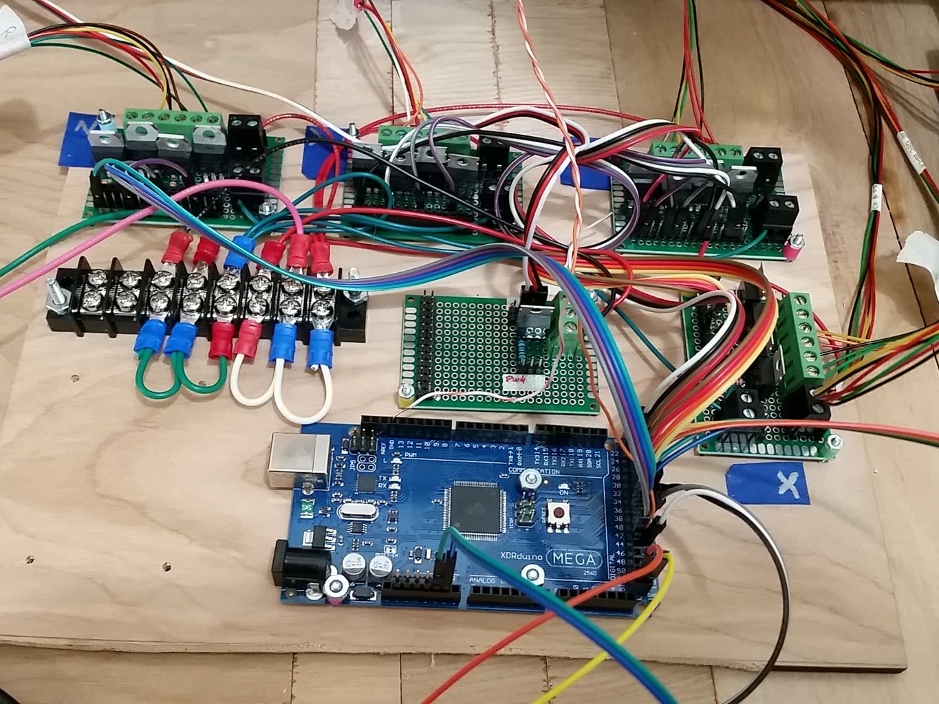


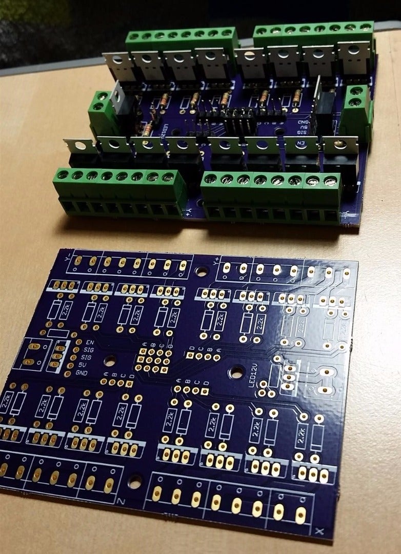
I built this circuit on plated perf boards, and it took about 4-5 hours. I laid out a board because I figured I would be building this claw machine again. The custom PCB makes the electronics steps faster, and much more organized. I used Eagle CAD to layout the board and had OSH Park fabricate the board. Fab costs are $10/sq inch, which will yield three PCBs (prototype price/quantity).
Whatever route you pick, take plenty of time to make your electronics clean. Mount your boards, secure psu, bundle wires, fasten to frame and make sure everything is accessible in case repairs are needed. Take into consideration how the TIP120 package will dissipate heat (heatsink, air cool, force air cool) if you decide to run things on 12V+.
Step 6: Gantry Design /Assembly


The drawings and photos explain how the gantry is constructed. The stepper motors and their user-friendly mounting holes influence 80% of this design. There is no cheating this section. Measure every part, draw it to scale. The gantry went through the most revisions, about 7 or 8.
The 2 'rollers' on the X gantry are 5mm shaft couplers. Sure, that's not what they are made for, but they work well. I tried 3D printing solid cylinders and tapping them so they would lock to the driving axle, but the shaft couplers worked better imo.
A very important design feature are the adjustable black rack rails the gantry rides on. The last photo points to these rails that can move in and out. These rails serve as the fudge factor compensator. This makes sure, that whatever the gantry width is (you only get so many chances to cut the aluminum) that we can make it work for our system. The rack rails can move in and out to fit the riding wheels (flanged bearings). They also adjust in case the frame is out of square, though I did not have this problem with the Al frame. If you build machine with wood make sure everything is square!
Step 7: Make the Claw (or Buy One....)


Initially I bought a claw, thinking I could save time. I bought some stamped metal claw off amazon with high hopes. I've seen the same kind everywhere so I figured it was worth the $18. It was junk. Tolerances were sloppy, rivets were loose, it didn't even fit standard size servos. I returned it and turned to my drawing board. This took a few weeks of testing and revising, but I made a claw of similar cantilever design that fits most generic servo motors. Key here is to use nylon lock washers so the claw does not disassemble itself after repeated use. I am very happy with the strength. I did add rubber bands to help with grip. Some candy packaging is rather slippery; the rubber bands add some friction (Twisters I am looking at you). The claw is made from .25 plywood, which keeps it light. Servo motor is 180 degree.
A number of people ask me, can you attached a standard claw to this? Yes. Although those claws use solenoids that need 50V and a few amps to drive them; knowing that interfacing them with this machine is simple. My claw runs off a medium sized 5V and 12V dual power supply. It was actually a PSU for a external CD-ROM drive. These are inexpensive (I actually found mine in the garbage). If you want to use a real amusement type claw, you'll need to drive it with the appropriate power (voltage + current) and this might add some unexpected cost. However you will get props in the cool factor.
Step 8: Logic Flow and Game Design

If you're going to write any code/ program. It is best to have a map. The diagram above shows how the game flows and highlights specific behaviors of my claw machine. (Of course I didn't make this before I started coding. Who does that?) Over a two week period I wrote most of the code. I tackled small chucks at a time and only when 'feature creep' started to find it's way into my brain ("Oh these lights should blink twice and then the prize chute should have lights and detect a prize then light up and....."), did I have to pull back and layout what does what.
The code I include in the next step is missing about 40% of the aforementioned diagram (machine behaviors). I am a firm believer that you will learn more if you try to write your own code. Sorry about the bad news!
I get a number of emails from students trying to build my claw machine as their senior project/ college something or whatever project. Come on people, put the effort in! Your professor knows how to use google... You don't want to get caught with copy and pasted code... On to the next step.
Good luck! :)
Step 9: Arduino Mega Code


The above diagram shows what this code does. If you want your machine to "goto home", blink lights and overall-have a more traditional behavior, you'll need to code this yourself. Trust me, it's for your own good.
By this point, you should be wiring the player controls to the machine if you haven't. You can make changes the layout depending on what type of game you want the claw machine to be; traditional or full control.
Attachments

Step 10: Custom Mounts / Custom Features


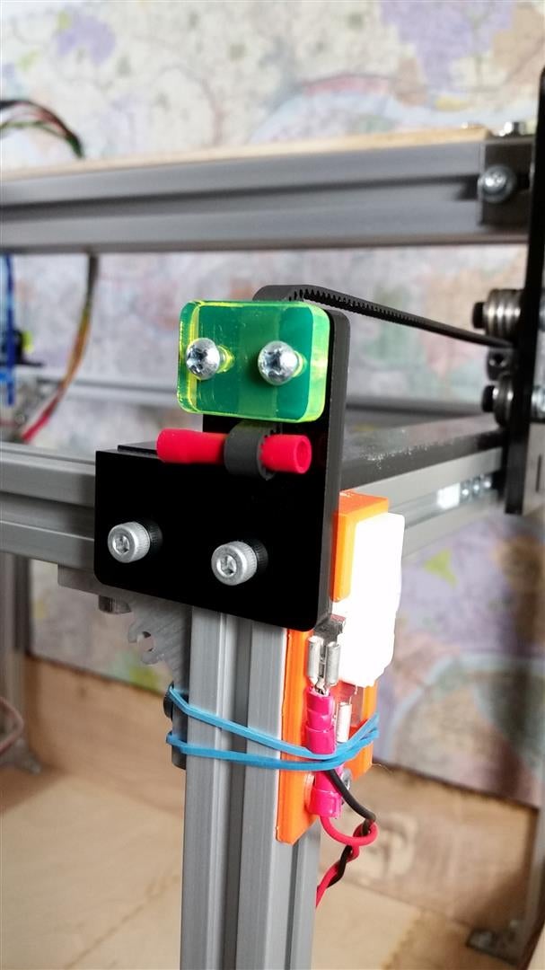
There are a few brackets and mounts that just can't be cut from 2D stock. Here are some brackets that I made to fit standard arcade microswitches. I made these brackets on a PrintrBot Simple Metal. I think it's a very good machine btw. These brackets+microswitches are now the limit switches on the machine.
A pulley was made to increase the diameter of the Z shaft. A larger diameter will wind (pull up) the claw faster. "Why not just increase the stepper rotation speed?" I tried this. Driving the stepper close to it's max velocity will result in loss of torque+skip steps when under load.
I also had to make a mount for my potentiometer (claw control) and some other brackets to mount buttons and take up slack in the GT2 belts.
Step 11: LED Lights (optional)


I attached 12V LED light strips to the underside of the gantry to give some light to the game. They are controlled via PWM with a TIP120. By now these SMD LED strips are rather common on eBay, but their effectiveness is not to be understated. Aside from making the pile of mixed candy look more appealing and illuminating the playfield, these LEDs also give visual cues for the claw game. The body LEDs turn off when game is idle or transitions to 'game over', turn dim when a quarter is inserted, go full brightness when the game is being played, and flash when "time expired" is displayed.
Step 12: WIN SOME CANDY!
The best part is playing the machine!
You could add some plexiglass to encase the machine and stop cheaters, but I went so far over budget that I will leave that for a later day...
Thanks for reading/watching!
More info is at my website retrobuiltgames.com
I hope to have this claw machine as a DIY kit sometime soon.

First Prize in the
Robotics Contest

Participated in the
Tech Contest

Participated in the
Make It Glow! Contest


