

Introduction: Arduino Controlled CNC / 3D Printer Hybrid


Mother Nature Makes ... We Build.
BuildersBot Fuses 3D Printing & CNC Milling Into One Builder’s Dream "3dprintingindustry.com"
The BuilderBot is an Open Design machine, that uses Open
Software and Open Hardware. It is a product of open projects such as the RepRap, Arduino and Repetier .
The objective of this instructable is to guide your way throw the entire making process of building a BuildersBot machine. An open design Arduino Controlled CNC Router that can also perform 3D printing.
The instructions will cover all areas such as design, mechanics, electronics and software.
But before you go any further take a look at machine's concept design:
And also the machine build photos and the machine in action:
Finally check out the insane effects of the RGB led's on BuildersBot:
Warning Viewer Discretion Advised (Strong Language)
Step 1: The BuildersBot OpenDesign (Sketchup)


To view the the machine in 3D just Download the attached sketch file and access the BuildersBot OpenSource Design (in metric system and is in 1 by 1 scale).
Use this design as much as possible for guidance during this instructable.
NOTE: Use trimble/google sketchup to open the file.

Step 2: List of Materials and Costs

In order to build a BuildersBot you will need the following list of "ingredients":
8 - SBR20UU CNC Linear Ball Bearing Support - 35€
4 - SBR16UU CNC Linear Ball Bearing Support - 20€
1 - Ballscrew with Fitted Anti Backlash Ballnut RM1605-C7: 350mm - 100€
1 - XD Coupling 25mm X 30mm Bore Size: 8mm to 12mm - 10€
3 - Motor coupling Bore Size: 8mm to 6mm - 15€
2 - SFC16 Precision ground round shaft with support (16 mm) - 30€
2 - SFC20 Precision ground round with shaft support (20 mm) - 70€
2 - SFC20 Precision ground round shaft with support (20 mm) - 60€
3 - Timing Belt 1790-5M-15 - 45€
1 - Shielded Ball Bearing 686-ZZ (Pack of 10) - 20€
6 - Metric Timing Pulley - 35€
1 - 15mm Aluminum plate - 50€
1 - Kress Milling Spindle 1050W - 150€
1 - 43mm Euro Neck Spindle Mount, Bracket Clamp for Kress Milling Spindle - 35€
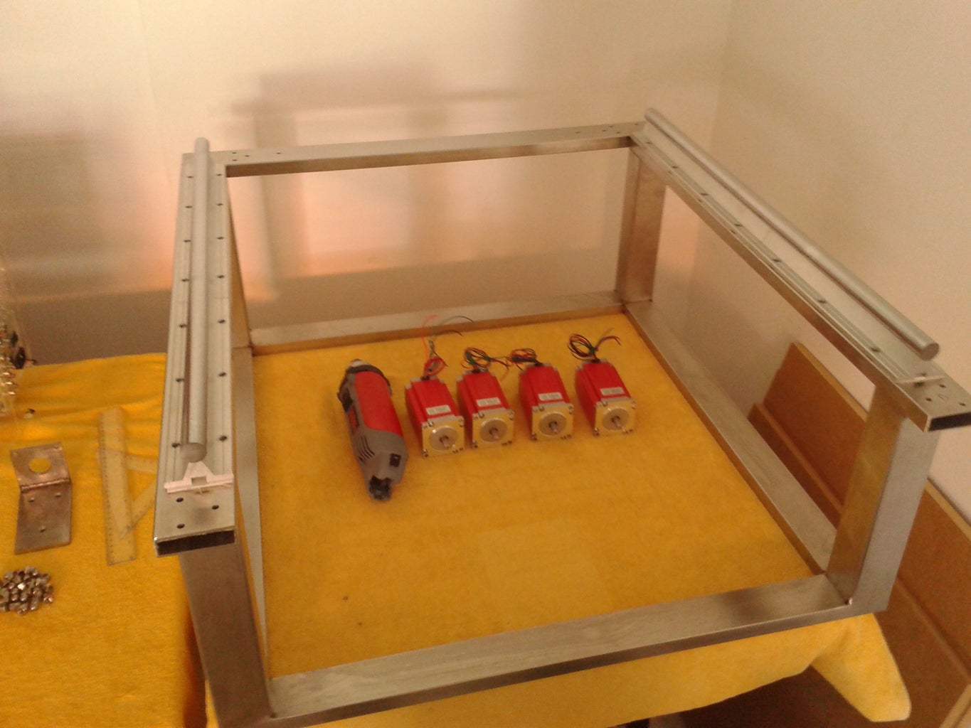
1 - 4 Nema 23 Stepper Motor 425oz + 4 microstepping Driver + Power Sup - 255€
1 - MIG Welded Stainless steal frame 125€
1 - Stainless Steal marine grade screws, washer, nuts etc - 50€
1 - 10mm Acrylic Case - 50 €
1 - Arduino Mega + Ramps 1.4 Board + LCD- 100€
1 - 12V power supply - 15€
1 - Complete Greg's extruder J-head hot end + motor + ABS extruder + endtops + hotbed - 100€
1 - Lock tight + lubricant + paint - 35€
1 - Wires, cables, tubs, connectors, plugs - 20€
2 - Low noise fans - 15€
1 - MDF board for the BuilderBot Bed - 15€
1 - 5 Meter RGB LED Stip - 30€
The total approximate cost of these items is around 1485€
Step 3: Understanding the 3 Dimensional Cartesian Coordinate System

"The 3 dimensional Cartesian coordinate system consists of three number lines, labelled X, Y and Z, set at 90 degree angles to each other. The origin, is where the three axes cross each other."
3D ... duh :)
The Buildersot works/moves within a 3 dimensional Cartesian coordinate System, allowing the machine to position its tool (drill bit or hot end) in any location inside the 3 dimensional work space.
The X axis will move the tool from left to right, the Y axis will move the tool from back to forth and finally the Z axis will move the tool up and down inside the work area.
In summary: The 3 dimensional work space is mapped using XYZ coordinates, this means that we can precisely control the position of the tool holder inside the work space.
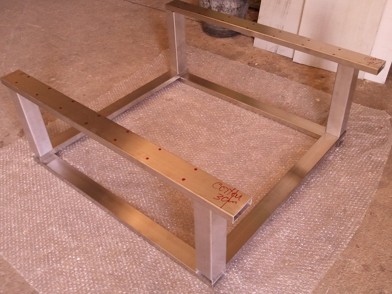
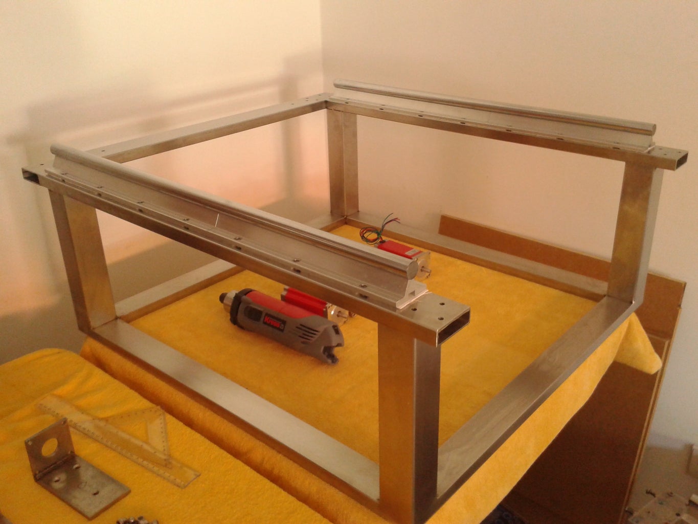
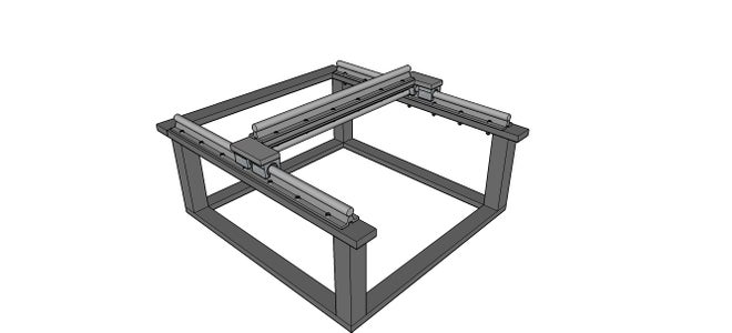
Step 4: The BuildersBot Stainless Steel Frame


The objective:
Build a frame made from rectangular and square stainless steel tubes.
Items needed:
The frame is composed by 11 stainless steel parts (for dimensions consult the 3d open design).
4 - rectangular tubes on the bottom of the chassis
4 - square tubs positioned vertically
3 - rectangular tubes on the top frame
Tools needed:
- TIG welder
- Angle grinder and cutting tool
- Drill machine
- Carbide drill bit ( 6.5mm )
Instructions:
1- Using a cutting tool:
- Cut 2 stainless steel rectangular tube with 50x20x750mm that will function as the bottom vertices of the frame
- Cut 2 stainless steel rectangular tube with 50x20x750mm that will function as the bottom vertices of the frame
- Cut 4 stainless steel square tubs with 50X50x250mm that will function as the vertical pillars of the frame
- Cut 1 rectangular stainless steel tube with 60x20x750mm (that will function as the bottom vertices of the frame)
- Cut 2 rectangular stainless steel tube with 60x20x750mm (that will function as the bottom vertices of the frame)
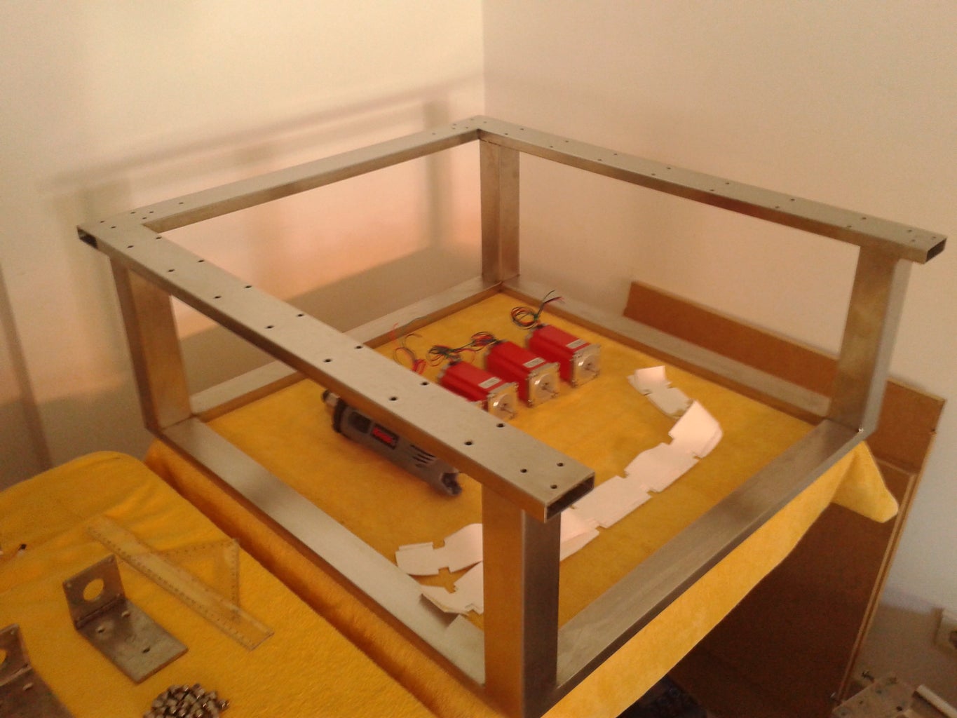
2 - Tap and drill 12 holes with 6.5mm diameter in both upper parallel rails (according to the position of the holes of the calibrated rail supports) (for distances consult the 3d sketch).
3 - Weld the 4 rectangular tubs that make the bottom frame. Be careful to align the tubes perfectly. Next weld the 4 vertical columns, and finally the 3 renaming top tubes that from an open frame.
4 - After welding all the tubes together, use angle grinder to trim the excess weld from the welding points.
5 - Clean the chassis with special acid for stainless steal , and finally polish it with any appropriate material.
Step 5: Y Axis - Guide System


The objective:
Equip the BuildersBot with a guide to minimize
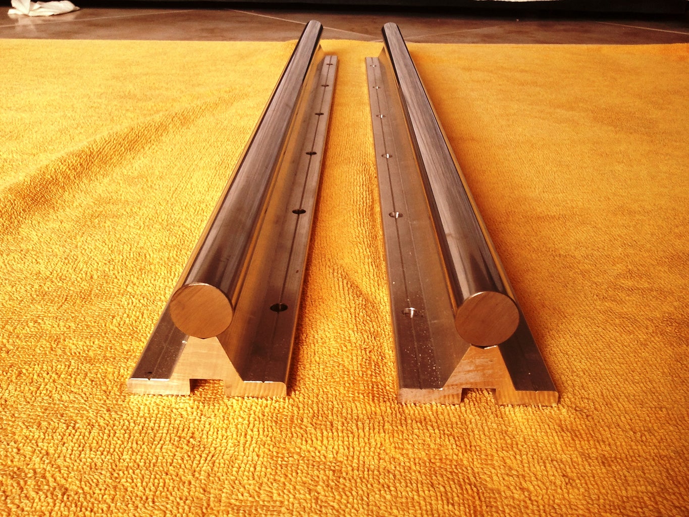
The Y axis guide system is composed by two parallel supported round rails. A round rail provides the linear guide path for bearing blocks to traverse along its length. This type of rail has precision tolerances is around 0.1mm per meter. The support of the rail is made from aluminum.
Items needed:
4 - SBR20UU Linear Ball Bearing Support, two for each rail
2 - 20mm diameter 700mm length sported round rails
28 - 6mm screws with 33mm length
28 - auto lock nuts
2 - sleeves of ultralearther
Tools needed:
- Screw driver
- Open wrench
- Level meter
- Ruler
Instructions:
To avoid propagation of vibration in the structure, isolate the stainless steel chassis from the aluminum rail support using some type of rubber (i used synthetic ultraleather).
Possition the round rail guides on top of the ultraleather and align the holes, then screw them in place, carefully align the 2 round rail's parallel to each other before final tightening, also try to adjust the level by adjusting the force on the screws. Be patient and try to achieve perfect alignment using a level meter and a ruller.
Step 6: X Axis - Guide System


The objective:
The X axis guide system is composed by two parallel supported round rails one under the other. In between the two supported rails are two L shaped 15mm aluminum plates(dimensions in sketchup file). These plates have 6.5mm holes in them in order to attache to the supported rails and also to the bearing block of the y axis (4 6.5mm holes for each bearing).
Items needed:
4 - SBR20UU Linear Ball Bearing blocks, two each side,
2 - 20mm diameter 600mm length sported round rails
24 - 6mm crews with 33mm length
24 - lock nuts.
Tools needed:
- Screw driver
- Open wrench
- Level meter
- Ruler
Instructions:
Before mounting the X Axis on top of the Y Axis, you need to insert 4 leaner bearing blocks on to the round rails, as shown in the figures.
Attach the round rail guides on top of the chssis and screw them in place, carefully align the 2 round rail's parallel to each and perfectly perpendicular to the Y axis other before final tightening.
Step 7: Y Axis - Transmission System


The objective:
The Y Axis transmission system is composed by a Timing Belt and Pulleys System. The Y Axis transmission system drives the the the tool holder up and down. The implementation used is a paired transmission system, this means that there are 2 Timing belts and 4 pulleys to drive the Y axis back and forth.
The System implemented has no reduction, these means that the driving pulley is the same diameter as the idler pulley. I have no performance problems with this setup.
Items needed:
2 - 1790-5M-15 Timing Belt
8 - 686-ZZ Shielded Ball Bearing
4 - 20-5M-15 Metric Timing Pulley
4 - Aluminum U shaped pulley support
4 - M6 calibrated shafts for the pulleys
12 - 4M Grub screws ( for the pulley )
2 - Motor couppling
Tools needed:
- Drill machine
- Screw tapper kit (5mm male drill)
- Angle grinder
Instructions:
- Prepare the pulleys by tapping M4 male screw (3 holes spaced by 120 degrees)
- Insert 3 4M grub screw in the tapped holes
- Drill a hole in the center of the pulley to allow the shaft to pass (6mm diameter hole)
- Make bearing housing inside the aluminum U shapes using a manual router end mill
- Insert the bearings inside the housings
- Mount the aluminum U shaped bearing housing on to the frame
- Tighten the belt around the 2 pulleys and lock them in position with good tension
- Attach motor coupling to pulley shaft
Step 8: X Axis - Transmission System


The objective:
The X Axis transmission system is composed by a Timing Belt and Pulleys System. The X Axis transmission system drives the tool holder left and right. The System implemented has no reduction, these means that the driving pulley is the same diameter as the idler pulley. I have no performance problems with this setup.
Items needed:
2 - 1790-5M-15 Timing Belt
8 - 686-ZZ Shielded Ball Bearing
4 - 20-5M-15 Metric Timing Pulley
4 - Aluminum U shaped pulley support
4 - M6 calibrated shafts for the pulleys
12 - 4M Grub screws ( for the pulley )
Tools needed:
- Drill machine
- Screw tapper kit (5mm male drill)
- Angle grinder
Instructions:
- Prepare the pulleys by tapping M4 male screw (3 holes spaced by 120 degrees)
- Insert 3 4M grub screw in the tapped holes - Drill a hole in the center of the pulley to allow the shaft to pass (6mm diameter hole)
- Make bearing housing inside the aluminum U shapes using a manual router end mill
- Insert the bearings inside the housings
- Mount the aluminum U shaped bearing housing on to the frame
- Tighten the belt around the 2 pulleys and lock them in position with good tension
- Attach motor coupling to pulley shaft
Step 9: Z Axis Guide and Transmission System


The objective:
The Z axis used in this machine has an unorthodox guide and transmission system. The guide system is mounted in a way that it will allow the Z axis to have 22 cm range. This is quite a big value for small CNC as this one, but it was built in purpose to allow for 3D printing big object. When the CNC is in action the CNC bed is risen to the appropriate height.
Items needed:
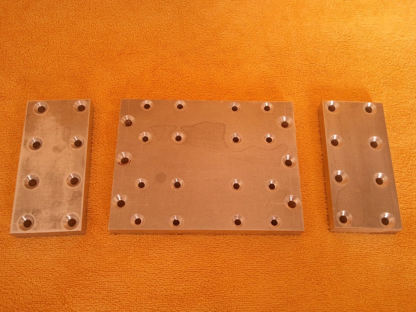
3 - 15mm Aluminum plates (for sizes please consult the sketchup design)
2 - Supported round rails (16mm)
1 - Ballscrew with Fitted Anti Backlash Ballnut 1605-C7: 350mm Total Length
4 - SBR16UU Bearing blocks
2 - 20mm bearings
1 - Coupling 25mm X 30mm ( Bore Size: 8mm to 12mm)
1 - Costume made part to attache the Ballnut to the X Axis "bearing wall"
Instructions:
- Cut the 15mm aluminum plate according the sketchup design. As a result you will have 2 small blocks an 1 bigger block of aluminum plate.
- Tap 6.5mm holes in the aluminum according to the design
- Than attach the round rails with support onto the bigger aluminum plate
- Insert the bearing into the housings of the smaller aluminum plates
- Position the ball-screw and ball nut in between the supported round rails and inside the bearings
- Calibrate the alignment of the rails and the ball-screw
Step 10: The Temporary CNC Bed Plate


The objective:
Build a work area for the Builderbot.
The CNC bed plate is made out of 2 MDF boards 20mm tick each. They where glued together using wood glue and let to dry for a day or so. The bed was then drilled in a 10cm square matrix of M8 pecked holes.
Note: Most MDF contains formaldehyde, this is a scientifically proven cancer causing agent. I don't recommend the use of MDF, i coated it thoroughly with varnish in order to isolate the material from the air in my workshop. As soon as i can i will change the bed with other type o wood, because i don't want to support this kind of materials.
The bed can be placed in different heights depending on the material to mill or object to print.
Step 11: The Electronics Enclosure


The objective:
Build an enclosure for the electronics
The BuildersBot electronics enclosure is made from 7 laser cut acrylic parts. All parts fit together to make the enclosure. The enclosure houses 4 Micro Stepping Drivers, three power supplies (36V, 36V and 12V) an Arduino Mega and a ramps 1.4 board and also 2 fans for cooling.
Items needed:
2 - 70x50x5mm Acrylic sheets
2 - Cooling fans
Tools needed:
- laser cutting machine
- Screw driver
Instructions:
The enclosure has rear holes for all exterior wire connections. All stepper drivers are mounted on a acrylic plate and positioned in the middle of the enclosure. The enclosure is closed using zip-ties. To enhance the enclosures visual presentation there are 4 blue LED's that light up the enclosure when power is on.
The CAD file:
Download the EletroboxV2.cdr CAD file in metric units.
Step 12: Wiring the Electronics

The objective:
Wire the electronics
Items needed:
- 4 Nema 23 Motor dual shaft 425oz-in
- 4 Driver 4.2A 128MicroDriver
- 3 Power Supplies (36V, 36V and 12V)
- 1 Arduino Mega
- 1 Ramps 1.4 Board (for CNC milling and 3D printing)
- Smart Controller LCD
- 6 End Stops (3 Wires)
- Solder
Tools needed:
- Soldering iron
- screw driver
- Wire cutter
- Digital multimeter
All the electric wiring can be done by following the attached diagram.
Step 13: Stepper Motor Installation - Red Theme


As you have may noticed in the final build photos the Builderbot has a red theme, the motor and the spindle where painted in red using height temperature spat paint. The cable carriers where also painted in red.
Step 14: CNC Routing Capabilities, Repetability and Resolution


Repetier CNC functionalities and Limitations ( work in progress ):
- Repetier firmware is able to interpret ARC Codes G2 and G3
- For my experience Repetier gcode interpreter does not recognize G83 (hole pecking function)
- To be continued as i explore the limitations and functionalities of the firmware
The BuildersBot technical CNC specs:
- Kress Spindle
- Working volume of 50x70x20 cm.
- Precision (to be calculated as soon as i get the tools)
Instructions for CNC Milling:
This is the CNC work flow protocol I use:
- Mount the Kress Spindle with a drill-bit no to the BuildersBot tool holder
- Prepare and align the CNC bed in all 4 corners
- Prepare the stock material to mill (Acrylic, wood, aluminium etc)
- Secure the stock material in place
- Turn the electronics power on
- Turn the Repetier Software on
- Home in the X and Y axis (according to stock material)
- Manually home in the Z axis (according to stock material)
- Load your GCode file into Repetier Software ( Generate a GCode File, using any CAM software )
- Turn the Spindle on
- Adjust Speed on Repetier (speed rate)
- Press Play to start milling
CNC milling resolution, repeatability in 10 mm Acrylic sheet using 2mm depth passes:
- Using a digital clipper the measured repeatability error is in the range of 0.1 - 0.3 mm (photos)
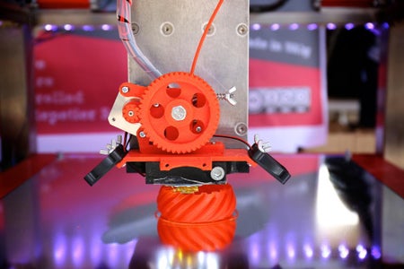
Step 15: 3D Printing


The objective:
Fit the BuilderBot with an extruder and filament holder that will allow it to perform 3D Printing.
This feature allows the printing of very big object (500x700x200 max volume)
The Z axis allows the printing of height objects, and the idea is also allow the fitting or other extruders that will come out in the future, such as metal and cement printing.
The extruder is mounted on the tip of the tool holder, it is a version of Greg's extruder and has a 0.5mm J-head hotend. It can be mounted or unmounted from the tool holder by simply unbolting 2 bolts.
The cable connections connect the extruders motor, the fan, the hotend resistor and the thermistor.
Step 16: Greg's Extruder Mount

The extruder mount price can be attached to the Builderbot using 3 bolts. It can house three 4cm fans and a Gregs extruder.
Attachments

Step 17: Configuring Repetier Firmware for Arduino Mega 2560

Repetier or Marlin Firmware for Arduino Mega implement G2 an G3 circular interpolation so they are good to use for CNC and 3D Printing. However they have limitations regarding pure CNC instructions such as pecking an other GCode's.
Download and install Arduino IDE Here: http://arduino.cc/en/main/software
Download and Repetier Firmware here: http://www.repetier.com/download/
Configuring the Repetier Firmware for CNC functionality:
After installing Arduino IDE, open it and use it to open the Repetier Firmware you have just download (repetier.ino file).
- Arduino IDE Tools Tab:
SelectBoard -Arduino Megra 2560 or MEGA ADK
- Navigate to the Configuration.h file and alter the following lines:
#define NUM_EXTRUDER 0
#define MOTHERBOARD 33
#define XAXIS_STEPS_PER_MM 128
#define YAXIS_STEPS_PER_MM 128
#define ZAXIS_STEPS_PER_MM 2560
#define HAVE_HEATED_BED false
#define ENDSTOP_PULLUP_X_MIN false
#define ENDSTOP_PULLUP_Y_MIN false
#define ENDSTOP_PULLUP_Z_MIN false
#define ENDSTOP_PULLUP_X_MAX false
#define ENDSTOP_PULLUP_Y_MAX false
#define ENDSTOP_PULLUP_Z_MAX false
#define ENDSTOP_X_MIN_INVERTING false
#define ENDSTOP_Y_MIN_INVERTING false
#define ENDSTOP_Z_MIN_INVERTING false
#define ENDSTOP_X_MAX_INVERTING false
#define ENDSTOP_Y_MAX_INVERTING false
#define ENDSTOP_Z_MAX_INVERTING true
#define MIN_HARDWARE_ENDSTOP_X true
#define MIN_HARDWARE_ENDSTOP_Y true
#define MIN_HARDWARE_ENDSTOP_Z true
#define MAX_HARDWARE_ENDSTOP_X true
#define MAX_HARDWARE_ENDSTOP_Y true
#define MAX_HARDWARE_ENDSTOP_Z true
#define Y_HOME_DIR -1
#define Z_HOME_DIR -1
#define max_software_endstop_x true
#define max_software_endstop_y true
#define max_software_endstop_z true
#define ENDSTOP_X_BACK_MOVE 5
#define ENDSTOP_Y_BACK_MOVE 5
#define ENDSTOP_Z_BACK_MOVE 0
#define ENDSTOP_Y_RETEST_REDUCTION_FACTOR 2
#define ENDSTOP_Z_RETEST_REDUCTION_FACTOR 2
#define ALWAYS_CHECK_ENDSTOPS true
#define X_MAX_LENGTH 500
#define Y_MAX_LENGTH 700
#define Z_MAX_LENGTH 200
#define MAX_FEEDRATE_X 200
#define MAX_FEEDRATE_Y 200
#define MAX_FEEDRATE_Z 5
#define HOMING_FEEDRATE_X 80
#define HOMING_FEEDRATE_Y 80
#define HOMING_FEEDRATE_Z 3
#define MAX_ACCELERATION_UNITS_PER_SQ_SECOND_X 1500
#define MAX_ACCELERATION_UNITS_PER_SQ_SECOND_Y 1500
#define MAX_ACCELERATION_UNITS_PER_SQ_SECOND_Z 100
#define MAX_TRAVEL_ACCELERATION_UNITS_PER_SQ_SECOND_X 3000
#define MAX_TRAVEL_ACCELERATION_UNITS_PER_SQ_SECOND_Y 3000
#define MAX_TRAVEL_ACCELERATION_UNITS_PER_SQ_SECOND_Z 100
Configuring the Repetier Firmware for 3D printing functionality:
#define NUM_EXTRUDER 1
#define EXT0_STEPS_PER_MM 413
#define HAVE_HEATED_BED true // if ture or else false
Attachments
Step 18: Repetier Host Software Configuration


To use the CNC or 3D printer functionality you need to install Repetier Host Software. In order to do so, use the following like to download the latest version:
http://www.repetier.com/download/
After installation open the Application and select Printer settings and make the following configurations:
CNC functionality:
- Connection Tab:
Port: (press refresh and update select the port)
Baud Rate:250000
- Printer Tab:
Travel Feed Rate: 4000mm/min
Z Axis Feed Rate: 200mm/min
- Printer Shape Tab:
Xmin: 0 mm
Xmax: 500 mm
Ymin: 0 mm
Ymax: 700 mm
Peint Area Width: 500mm
Print Area Depth: 700mm
Print Area Height: 200mm
3D Printing functionality:
- Connection Tab:
Port: (press refresh and update select the port)
Baud Rate:250000
- Printer Tab:
Travel Feed Rate: 4000mm/min
Z Axis Feed Rate: 200mm/min
- Printer Shape Tab:
Xmin: 0 mm
Xmax: 500 mm
Ymin: 0 mm
Ymax: 600 mm
Peint Area Width: 500mm
Print Area Depth: 600mm
Print Area Height: 200mm
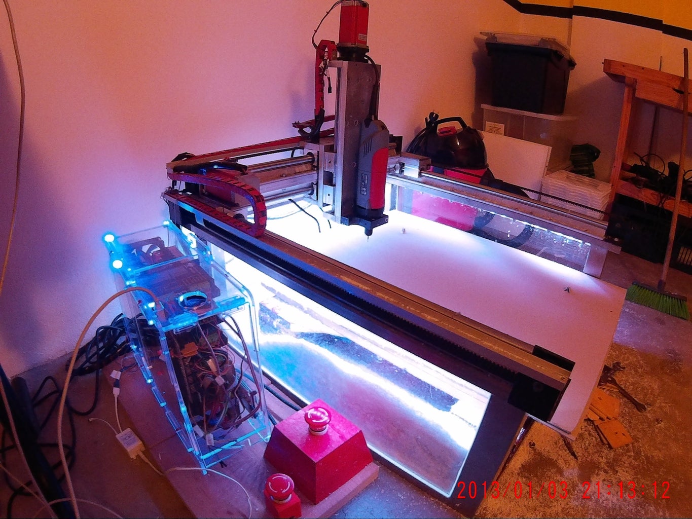
Step 19: BuildersBot LED's


The BuilderBot has a 5 meter 5050 SMD RGB led strip attached to the inferior part of the upper frame chassis. The led strip is glued using strong double sided tape. It serves the propose of lightning the BuildersBot workspace and also Pimping the machine to its max.
Warning Viewer Discretion Advised (Strong Language)
Warning Viewer Discretion Advised (Strong Language)
Step 20: Buildersbot at the Lisbon Mini Maker Faire


The Buildersbot was present at the Lisbon Mini Maker Faire 2014.
Check out my latest project at www.zenvow.com

First Prize in the
Epilog Challenge VI

Runner Up in the
Metal Contest


