

Introduction: Arduino Controlled Flashing Christmas Fairy Lights With Jingle Bells


As my first Arduino project I wanted to make something impressive but not too challenging. I entered a Christmas Hack with this project and won it! People love Christmas lights.
By the end of this you will have a set of christmas fairy lights that flash in time to jingle bells as can be seen in the attached video. Feel free to modify it and make it your own once you have completed these steps.
During this tutorial I have provided serveral links to Arduino's own tutorials and more about Arduino can be found here.
No soldering required.
Hovering over the image squares gives you more information.
Total time to complete: 2 hours (you do not need to complete all of this in one sitting)
Please note that as always you will need a computer with USB capabilities to program your Arduino.
Step 1: Things you will need
Step 2: Connecting up the LEDs
Step 3: Making the LEDs blink
Step 4: Setting up the speaker for Jingle Bells
Step 5: Code for Jingle Bells
Step 6: Making the LEDs flash with the sound
Step 7: Starting and stopping with a button
Step 8: Setting up your fairy lights
Step 9: Connecting your relay shield
Step 10: Testing your relay shield
Step 11: Connecting your fairly lights
Step 12: Finished product
Step 1: Things You Will Need:


- Arduino Uno (£22.19)
- 9 V Mains Power Supply (500 mA minimum, 2.1mm center-positive plug) (£6.72)
- USB cable type A Male to type B Male (£8.93)
Circuit components
- mini push button (£3.20)
- LED (£2.89 for 75)
- 150 ohm resistor (£1.04 for 100) (colour code = brown, green, brown, gold)
- 100 ohm resistor (£1.02 for 100 ) (colour code = brown, black, brown, gold)
- 10 K ohm resistor (£1.00 for 100 ) - missing from images (colour code: brown, black , orange, gold)
- Male to Male jumper pins (£5.99)
- 8-ohm speaker with cable (£2.48)
Hardware
- Solderless breadboard 400 tie points contacts (£2.79)
- 3A Terminal Block (£2.09)
- Multifunctional Fairy lights : They must have two or more sets of lights that switch on independently (£14.99)
- Relay shield: Note. If you use a module shield you will need male to female jumper pins (£25.61)
Tools
- Wire strippers (£2.68)
- Electrical tape (£1)
- Miniature flathead screw driver (£2) - This will be used for the relay shield and terminal block
Arduino : £37.84
Circuit Components: £18.62
Hardware: £44.48
Tools : £5.68
£106.62
Step 2: Connecting Up the LEDs


- 150 ohm resistor (colour code = brown, green, brown, gold)
- LED
- 3 * Jumper Pins
- Arduino
- Breadboard
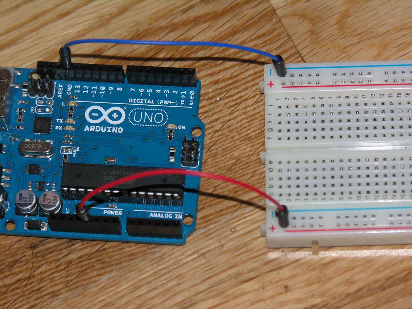
Supplying power to the Breadboard
- Attach a jumper pin from the Arduino 5V to the red positive line on the breadboard
- Attach a jumper pin from the Arduino GND to the blue negative line on the breadboard
Connecting up the LED
- Put the 2 legs of the LED in the breadboard either side of the centre line ( you may have to bend the legs slightly)
- LEDs have a right way and a wrong way, you will notice that the LED legs are different lengths. The short leg is negative while the longer leg is positive.
- Connect the resistor with the short leg of the LED and the negative (blue) line, making sure the resistor and LED leg are on the same row.
- Connect the other leg of the LED to pin number 13 on the Arduino using your last jumper pin
Step 3: Making the LEDs Blink


- USB cable
Now that your LED is setup, we need to write some code in order to make it blink.
- Download and install the Arduino software
- Open the programme, you should see a window like the one above.
- Makes sure that Tools -> Board is set to your selected Arduino type (in this case Arduino Uno)
- Click the open button (annotated on the picture) and select Basic -> Blink
- Connect your Arduino to your computer using the USB cable
- Make sure that Tools -> Serial Port is set to /dev/tty.usbmodem or /dev/cu.usbmodem as we are connected with our USB cable, not with bluetooth
- Click the upload to Arduino button
- If it has uploaded successfully you will see 'Done uploading'
When the pin is set to HIGH, the LED is switched on.
When the pin is set to LOW, the LED is switch off.
If your LED is connected properly it should now be flashing on and off as demonstrated in the video.
Note. the Arduino needs to be plugged in to the computer or mains in order to have power and run the demo.
/*<br>  Blink
  Turns on an LED on for one second, then off for one second, repeatedly.

  This example code is in the public domain.
 */

// Pin 13 has an LED connected on most Arduino boards.
// give it a name:
int led = 13;


// the setup routine runs once when you press reset:
void setup() {
  // initialize the digital pin as an output.
  pinMode(led, OUTPUT);
}


// the loop routine runs over and over again forever:
void loop() {
  digitalWrite(led, HIGH);   // turn the LED on (HIGH is the voltage level)
  delay(1000);               // wait for a second
  digitalWrite(led, LOW);    // turn the LED off by making the voltage LOW
  delay(1000);               // wait for a second
}
Step 4: Setting Up the Speaker for Jingle Bells


- 100 ohm resistor (colour code = brown, black, brown, gold)
- 8 ohm speaker
- 1 * Jumper Pins
Connecting up your speaker - The Arduino tone tutorial can be found here
- Disconnect the USB from the Arduino
- Attach one end of the speaker (using the cable attached to the speaker) to the blue negative line of the breadboard.
- Attach the other end to an empty row on the breadboard (making sure it is not on the same row as the LED)
- Attach the 100 ohm resistor along the same row as the speaker cable
- Attach the other end of the resistor row to pin 9 on the Arduino, using the jumper pin
In the next step you will see how to code the speaker to make it play jingle bells
Step 5: Code for Jingle Bells

- USB cable
- In your Arduino programme, press the new button.
- Copy and paste in the code below. The example for Arduino playMelody code can be found here , we have changed it slightly to play Jingle Bells.
- Attach the USB cable to your Arduino.
- Press the upload button.
// TONES  ========================================== // Start by defining the relationship between
 //       note, period, &  frequency.
 #define  C     2100
 #define  D     1870
 #define  E     1670
 #define  f     1580    // Does not seem to like capital F
 #define  G     1400
 // Define a special note, 'R', to represent a rest
 #define  R     0
 // SETUP ============================================
 // Set up speaker on a PWM pin (digital 9, 10 or 11)
 int speakerOut = 9;
 // Do we want debugging on serial out? 1 for yes, 0 for no
 int DEBUG = 1;
 void setup() {
   pinMode(speakerOut, OUTPUT);
   if (DEBUG) {
     Serial.begin(9600); // Set serial out if we want debugging
   }
 }
 // MELODY and TIMING  =======================================
 //  melody[] is an array of notes, accompanied by beats[],
 //  which sets each note's relative length (higher #, longer note)
 int melody[] = {E, E, E,R,
 E, E, E,R,
 E, G, C, D, E, R,
 f, f, f,f, f, E, E,E, E, D ,D,E, D, R, G ,R,
 E, E, E,R,
 E, E, E,R,
 E, G, C, D, E, R,
 f, f, f,f, f, E, E, E,  G,G, f, D, C,R };
 int MAX_COUNT = sizeof(melody) / 2; // Melody length, for looping.
 // Set overall tempo
 long tempo = 10000;
 // Set length of pause between notes
 int pause = 1000;
 // Loop variable to increase Rest length
 int rest_count = 100; //<-BLETCHEROUS HACK; See NOTES
 // Initialize core variables
 int tone_ = 0;
 int beat = 0;
 long duration  = 0;
 // PLAY TONE  ==============================================
 // Pulse the speaker to play a tone for a particular duration
 void playTone() {
   long elapsed_time = 0;
   if (tone_ > 0) { // if this isn't a Rest beat, while the tone has
     //  played less long than 'duration', pulse speaker HIGH and LOW
     while (elapsed_time < duration) {
       digitalWrite(speakerOut,HIGH);
       delayMicroseconds(tone_ / 2);
       // DOWN
       digitalWrite(speakerOut, LOW);
       delayMicroseconds(tone_ / 2);
       // Keep track of how long we pulsed
       elapsed_time += (tone_);
     }
   }
   else { // Rest beat; loop times delay
     for (int j = 0; j < rest_count; j++) { // See NOTE on rest_count
       delayMicroseconds(duration);
     }
   }
 }
 // LET THE WILD RUMPUS BEGIN =============================
 void loop() {
  for (int i=0; i<MAX_COUNT; i++) {
    tone_ = melody[i];
    beat = 50;

    duration = beat * tempo; // Set up timing

    playTone();
    // A pause between notes...
    delayMicroseconds(pause);
  }
 }
Attachments
Step 6: Making the LEDs Flash With the Sound
- USB cable
This is much the same as the previous code, however we have added the LED back in as in the blink function. It will turn on when the note plays and off when the note stops
// TONES  ========================================== // Start by defining the relationship between
//       note, period, &  frequency.
#define  C     2100
#define  D     1870
#define  E     1670
#define  f     1580    // Does not seem to like capital F
#define  G     1400
// Define a special note, 'R', to represent a rest
#define  R     0
// SETUP ============================================
// Set up speaker on a PWM pin (digital 9, 10 or 11)
int speakerOut = 9;
int led = 13;
// Do we want debugging on serial out? 1 for yes, 0 for no
int DEBUG = 1;
void setup() {
   pinMode(speakerOut, OUTPUT);
   pinMode(led, OUTPUT);
   if (DEBUG) {
     Serial.begin(9600); // Set serial out if we want debugging
   }
}
// MELODY and TIMING  =======================================
//  melody[] is an array of notes, accompanied by beats[],
//  which sets each note's relative length (higher #, longer note)
int melody[] = {E, E, E,R,
E, E, E,R,
E, G, C, D, E, R,
f, f, f,f, f, E, E,E, E, D ,D,E, D, R, G ,R,
E, E, E,R,
E, E, E,R,
E, G, C, D, E, R,
f, f, f,f, f, E, E, E,  G,G, f, D, C,R };
int MAX_COUNT = sizeof(melody) / 2; // Melody length, for looping.
// Set overall tempo
long tempo = 10000;
// Set length of pause between notes
int pause = 1000;
// Loop variable to increase Rest length
int rest_count = 100; //<-BLETCHEROUS HACK; See NOTES
// Initialize core variables
int tone_ = 0;
int beat = 0;
long duration  = 0;
// PLAY TONE  ==============================================
// Pulse the speaker to play a tone for a particular duration
void playTone() {
   long elapsed_time = 0;
   if (tone_ > 0) { // if this isn't a Rest beat, while the tone has
     //  played less long than 'duration', pulse speaker HIGH and LOW
     digitalWrite(led, HIGH);
     while (elapsed_time < duration) {
       digitalWrite(speakerOut,HIGH);
       delayMicroseconds(tone_ / 2);
       // DOWN
       digitalWrite(speakerOut, LOW);
       delayMicroseconds(tone_ / 2);
       // Keep track of how long we pulsed
       elapsed_time += (tone_);
     }
   digitalWrite(led, LOW);
   }
   else { // Rest beat; loop times delay
     for (int j = 0; j < rest_count; j++) { // See NOTE on rest_count
       delayMicroseconds(duration);
     }
   }
}
// LET THE WILD RUMPUS BEGIN =============================
void loop() {
  for (int i=0; i<MAX_COUNT; i++) {
    tone_ = melody[i];
    beat = 50;

    duration = beat * tempo; // Set up timing

    playTone();
    // A pause between notes...
    delayMicroseconds(pause);
  }
}
Attachments
Step 7: Starting and Stopping With a Button


- mini push button
- 10 K ohm resistor (colour code: brown, black , orange, gold)
- 3 * jumper pins
- USB cable
Connecting up your button - The Arduino button tutorial can be found here
- Disconnect the USB from the Arduino
- Place the button on the centre line of the breadboard - you will notice the button fits one way but not the other.
- Connect one of the legs to the red positive line using a jumper pin
- Connect the 10K resistor from the other leg on the same side, making sure it is parallel to the red and blue lines (see image above)
- Connect the other side of the resistor to the blue negative line
- On the other side of the button, connect the leg on the the same row as the resistor to pin 2 on the Arduino
- Copy and paste the code into a new Arduino file
- Attach the USB cable to the Arduino
- Upload the file
#define  C     2100
#define  D     1870
#define  E     1670
#define  f     1580    // Does not seem to like capital F
#define  G     1400
// Define a special note, 'R', to represent a rest
#define  R     0


// SETUP ============================================
// Set up speaker on a PWM pin (digital 9, 10 or 11)
int speakerOut = 9;
int led = 13;
int buttonPin = 2;

void setup() {
  pinMode(speakerOut, OUTPUT);
  pinMode(led, OUTPUT);
  pinMode(buttonPin, INPUT);
}

// BUTTON

// Variables will change:
int on = LOW;         // the current state of the output pin
int buttonState;             // the current reading from the input pin
int lastButtonState = LOW;   // the previous reading from the input pin

// the following variables are long's because the time, measured in miliseconds,
// will quickly become a bigger number than can be stored in an int.
long lastDebounceTime = 0;  // the last time the output pin was toggled
long debounceDelay = 50;    // the debounce time; increase if the output flickers


// MELODY and TIMING  =======================================
//  melody[] is an array of notes, accompanied by beats[],
//  which sets each note's relative length (higher #, longer note)
int melody[] = {E, E, E,R,
E, E, E,R,
E, G, C, D, E, R,
f, f, f,f, f, E, E,E, E, D ,D,E, D, R, G ,R,
E, E, E,R,
E, E, E,R,
E, G, C, D, E, R,
f, f, f,f, f, E, E, E,  G,G, f, D, C,R };


int MAX_COUNT = sizeof(melody) / 2; // Melody length, for looping.

// Set overall tempo
long tempo = 10000;
// Set length of pause between notes
int pause = 1000;
// Loop variable to increase Rest length
int rest_count = 30;

// Initialize core variables
int tone_ = 0;
int beat = 0;
long duration  = 0;

// PLAY TONE  ==============================================
// Pulse the speaker to play a tone for a particular duration
void playTone() {
  long elapsed_time = 0;
  if (tone_ > 0) { // if this isn't a Rest beat, while the tone has
    digitalWrite(led, HIGH);
    //  played less long than 'duration', pulse speaker HIGH and LOW
    while (elapsed_time < duration) {

      digitalWrite(speakerOut,HIGH);
      delayMicroseconds(tone_ / 2);

      // DOWN
      digitalWrite(speakerOut, LOW);
      delayMicroseconds(tone_ / 2);

      // Keep track of how long we pulsed
      elapsed_time += (tone_);
    }
     digitalWrite(led, LOW);

  }
  else { // Rest beat; loop times delay
    for (int j = 0; j < rest_count; j++) { // See NOTE on rest_count
      delayMicroseconds(duration);
    }
  }
}


void jingleBells(int i){
  // Set up a counter to pull from melody[] and beats[]
    tone_ = melody[i];
    beat = 50;
    duration = beat * tempo; // Set up timing
    playTone();
    // A pause between notes...
    delayMicroseconds(pause);
}


void checkOn(int reading){
  // check to see if you just pressed the button
  // (i.e. the input went from LOW to HIGH),  and you've waited
  // long enough since the last press to ignore any noise:

  // If the switch changed, due to noise or pressing:
  if (reading != lastButtonState) {
    // reset the debouncing timer
    lastDebounceTime = millis();

   // toggles the ledState variable each time the button is pressed
      if (buttonState == HIGH) {
      on = !on;
    }
  }

  if ((millis() - lastDebounceTime) > debounceDelay) {
    // whatever the reading is at, it's been there for longer
    // than the debounce delay, so take it as the actual current state:
    buttonState = reading;
  }
}

// LET THE WILD RUMPUS BEGIN =============================
void loop() {
     // read the state of the switch into a local variable:
  int reading = digitalRead(buttonPin);

  checkOn(reading);

    if(on){
     for (int i=0; i<MAX_COUNT; i++) {
        int loopReading = digitalRead(buttonPin);
         jingleBells(i);
        if(loopReading != reading){
          on = !on;
          break;
        }
     }
   }

  // save the reading.  Next time through the loop,
  // it'll be the lastButtonState:
  lastButtonState = reading;
}
Attachments
Step 8: Setting Up Your Fairy Lights


- Christmas fairy lights
- Wire strippers
- Small flat head screwdriver
- Terminal block
The fairy lights I bought had 3 wires going into the light control box, yours might have a different number so adjust accordingly.
First you will need to determine what cable is what, in my case I had:
- Cable controlling red and blue lights
- Cable controlling green and orange lights
- Ground cable
How to determine the cables:
- Plug the lights in to the mains so they are on
- Switch through the light control box settings so all the lights are on constantly (we want to control the lights with our Arduino and don't want the light control box interfering)
- UNPLUG THE LIGHTS FROM THE MAINS ( we are about to cut the wires and don't want to get a shock!)
- Cut one of the wires between the light control box and the lights
- Plug the lights back in to the mains
- If the red and blue lights go off, this wire controls the red and blue lights
- If the green and orange lights go off, this wire controls the green and orange lights
- If all the lights go off, this is the ground cable
- UNPLUG THE LIGHTS FROM THE MAINS
- Use the wire strippers to strip some of the plastic off exposing the wire and twist the wires together
- Using the Terminal Block attach the wires back together
- Repeat this step for the other cables keeping note of which is the ground cable
Step 9: Connecting Your Relay Shield


- Relay Shield
- Electrical tape
Wikipedia explains that a relay is
An electrically operated switch. Many relays use an electromagnet to operate a switching mechanism mechanically, but other operating principles are also used. Relays are used where it is necessary to control a circuit by a low-power signal (with complete electrical isolation between control and controlled circuits), or where several circuits must be controlled by one signal.We need it in this case as we are trying to control high-power mains fairly lights with Arduino's low-power signal.
The Relay Shield that I purchesed consisted of the boards and pins and sits on top of the Arduino. This means that we need to take the out the pins connected to the Arduino and remember what jumper pins were connected to what Arduino pin number.
Disconnect the USB from the Arduino
To make sure the Relay Shield does not touch the Arduino USB port, place a couple strips of electrical tape to cover it.
Please view the images on how to attach the Relay Shield to the Arduino.
The Relay connection to the Arduino wasn't great so I used an elastic band to hold them together. If you do have access to soldering equipment, you can solder the relay shield headers on to the relay shield. This should give it a better connection.
As we are going to be putting in the fairy lights next , we can remove the LED. This was just an intermediate step.
Once the Relay Shield is connected we can put the jumper pins in to the Relay Shield pins holes.
- The Relays use pins 7, 6, 5 and 4 so make sure you don't use any of these
- Pin 7 = Relay 1
- Pin 6 = Relay 2
- Pin5 = Really 3
- Pin 4 = Relay 4
- Pin 9 - Speaker
- 5V Pin - Positive
- GND Pin - Negative
- Pin 2 - Button
Step 10: Testing the Relay
- USB cable
- Unplug the speaker connection to the shield (this is just temporary so we can hear the relay switch)
- Upload the code to your Arduino
- Press the button on your breadboard.
- You should hear the relays click on and off (shown in the video). You may need to wiggle the pins connecting the relay shield to the Arduino a little until both relays are clicking on and off alternatively.
- Once we know this is working we can plug the speakers back in.
#define  C     2100
#define  D     1870
#define  E     1670
#define  f     1580    // Does not seem to like capital F
#define  G     1400
// Define a special note, 'R', to represent a rest
#define  R     0


// SETUP ============================================
// Set up speaker on a PWM pin (digital 9, 10 or 11)
int speakerOut = 9;
int green = 4;
int red = 7;
int buttonPin = 2;

void setup() {
  pinMode(speakerOut, OUTPUT);
  pinMode(green, OUTPUT);
  pinMode(red, OUTPUT);
  pinMode(buttonPin, INPUT);

  digitalWrite(green, LOW);

}

// BUTTON

// Variables will change:
int on = LOW;         // the current state of the output pin
int buttonState;             // the current reading from the input pin
int lastButtonState = LOW;   // the previous reading from the input pin

// the following variables are long's because the time, measured in miliseconds,
// will quickly become a bigger number than can be stored in an int.
long lastDebounceTime = 0;  // the last time the output pin was toggled
long debounceDelay = 50;    // the debounce time; increase if the output flickers


// MELODY and TIMING  =======================================
//  melody[] is an array of notes, accompanied by beats[],
//  which sets each note's relative length (higher #, longer note)
int melody[] = {E, E, E,R,
E, E, E,R,
E, G, C, D, E, R,
f, f, f,f, f, E, E,E, E, D ,D,E, D, R, G ,R,
E, E, E,R,
E, E, E,R,
E, G, C, D, E, R,
f, f, f,f, f, E, E, E,  G,G, f, D, C,R };


int MAX_COUNT = sizeof(melody) / 2; // Melody length, for looping.

// Set overall tempo
long tempo = 10000;
// Set length of pause between notes
int pause = 1000;
// Loop variable to increase Rest length
int rest_count = 30;

// Initialize core variables
int tone_ = 0;
int beat = 0;
long duration  = 0;

// PLAY TONE  ==============================================
// Pulse the speaker to play a tone for a particular duration
void playTone(int colour) {
  long elapsed_time = 0;
  if (tone_ > 0) { // if this isn't a Rest beat, while the tone has
    digitalWrite(colour, HIGH);
    //  played less long than 'duration', pulse speaker HIGH and LOW
    while (elapsed_time < duration) {

      digitalWrite(speakerOut,HIGH);
      delayMicroseconds(tone_ / 2);

      // DOWN
      digitalWrite(speakerOut, LOW);
      delayMicroseconds(tone_ / 2);

      // Keep track of how long we pulsed
      elapsed_time += (tone_);
    }
     digitalWrite(colour, LOW);

  }
  else { // Rest beat; loop times delay
      digitalWrite(colour, HIGH);
    for (int j = 0; j < rest_count; j++) { // See NOTE on rest_count
      delayMicroseconds(duration);
    }
      digitalWrite(colour, LOW);
  }
}


int colour = green;

void jingleBells(int i){
  // Set up a counter to pull from melody[] and beats[]
    tone_ = melody[i];
    beat = 50;
    duration = beat * tempo; // Set up timing

      if(colour == green){
        colour = red;
        playTone(red);
      }else{
        colour = green;
        playTone(green);
      }


    // A pause between notes...
    delayMicroseconds(pause);
}


void checkOn(int reading){
  // check to see if you just pressed the button
  // (i.e. the input went from LOW to HIGH),  and you've waited
  // long enough since the last press to ignore any noise:

  // If the switch changed, due to noise or pressing:
  if (reading != lastButtonState) {
    // reset the debouncing timer
    lastDebounceTime = millis();

   // toggles the ledState variable each time the button is pressed
      if (buttonState == HIGH) {
      on = !on;
    }
  }

  if ((millis() - lastDebounceTime) > debounceDelay) {
    // whatever the reading is at, it's been there for longer
    // than the debounce delay, so take it as the actual current state:
    buttonState = reading;
  }
}

// LET THE WILD RUMPUS BEGIN =============================
void loop() {
     // read the state of the switch into a local variable:
  int reading = digitalRead(buttonPin);

  checkOn(reading);

    if(on){
     for (int i=0; i<MAX_COUNT; i++) {
        int loopReading = digitalRead(buttonPin);
         jingleBells(i);
        if(loopReading != reading){
          on = !on;
          break;
        }
     }
   }

  // save the reading.  Next time through the loop,
  // it'll be the lastButtonState:
  lastButtonState = reading;
}
Attachments
Step 11: Connecting Your Fairly Lights

- Small flat head screwdriver
Once our relay is set up it is time to connect the fairy lights.
Since we are controlling pin 4 and pin 7 we need to make sure that we are using the corresponding relays 4 and 1 (we will only be using 2 of the relays out of the 4 as we only have 2 sets of lights to switch on and off).
- Make sure the fairy lights are NOT plugged in to the mains
- Relays have 3 connections
- Relay switch is default open (no connection)
- Common - connected if either default open or closed
- Relay switch is default closed (connection)
- Unscrew your first set of light cables from the terminal block (making sure it is not the ground cable)
- Screw in one end to common relay point
- Screw end the other end to the open relay point
- Repeat for your other light cable (again making sure it is not the ground cable) in to the other set relay
- Keep the ground cable connected with the terminal block.
You are now all set up and ready to test it!
Step 12: Finished Product
You will need:
- USB cable
- Power cable
You now have a finished product!
Instead of using the USB to power the Arduino we can now plug it into the mains (as we no longer need to change the code) as well as the Fairy lights.

Runner Up in the
Holiday Contest

Participated in the
Hardware Hacking

Participated in the
Supercharged Contest

Participated in the
Make It Glow Contest


