

Introduction: Arduino Controlled Wind Chimes


The soothing effects of chimes normally depend upon the wind, but this wind chime is Arduino powered.
Rather than wait for the wind to blow, it is possible to excite a series of tuned pipes using solenoids controlled by an Arduino program (sketch). I will discuss my design and the many factors that entered into its creation.
Yes, by adding a speaker to the Arduino, a simulated wind chime can be created, but nothing sounds as good as the real mechanical version.
Step 1: The Chimes Themselves

My original prototype chime player utilized some anodized aluminum tubing purchased from a Chinese source that were all pre-cut to a fixed length and drilled with a hole to hang them. They were all 17 cm in length and therefore had to be cut to various lengths to produce the correct notes. A web site that discusses ALL aspects of wind chime design is by Lee Hite . It is an amazing collection of everything you ever wanted to know about chimes and provided much insight into my design.
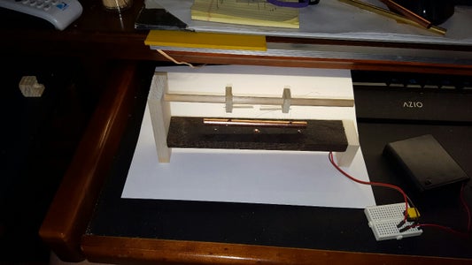
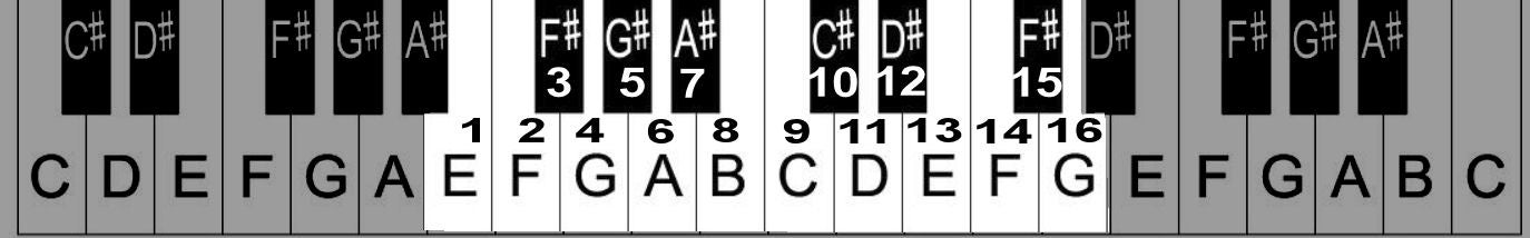
I determined that my chimes would primarily be excited in their first natural frequency and made a simple frame to allow me to "ring" each chime and measure its frequency. A free computer program (Audacity), allows recording of the sound of a "struck" chime and you can easily determine its fundamental frequencies. A great reference chart for frequencies of the equal tempered scale can be found here.
For the 17cm long tube I had, I determined that its first natural frequency was 1661 hz. which was G#6 in the key signature of "C". I decided to tune my first chime player to a different key signature so that the first chime would represent an "A" note. Since I wanted to use only 8 chimes, the subsequent chimes would be tuned to B,C,D,E,F,G,&A.
Rather than go through lengthy calculations, I found it easier to simply cut a tube at a different length and measure its fundamental frequency. Then some simple math comes into play.
The basic equation for the vibration of tube looks something like this...
Freq= (Blah,Blah..Blah) / (Tube length) squared.
Since the tubes were of the same material and only the length varied, a simple equation can be made to determine the length of tube required to produce any required frequency.
(Length 2)= (Length 1) * Sqr Root (Freq 1/ Freq 2).
Easy to compute on a spread sheet.
While it appears possible to compute all the required lengths at once, I found it better to continuously recompute the next required length from the previous one. Rather than go into details regarding the 8 note chime player, let me go into details of the 16 note player.
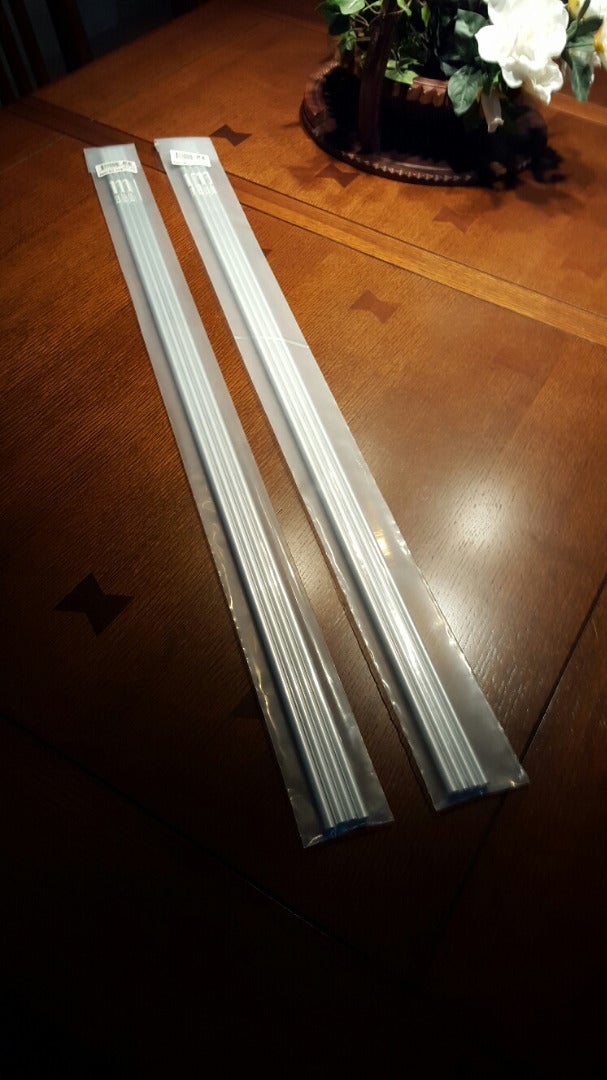
K & S Engineering produces thin wall aluminum tubing, 5/16"diameter, available in 36" lengths. It is sold in a package of 4 from Amazon for about $10.50 plus shipping. It is enough material to produce16 tuned chime tubes.
While the 8 note player was nice, there were many songs that had too great a range or included sharps or flats that the 8 note player couldn't handle. The 16 note player was tuned in the Key of C with the lowest chime at a frequency of 2637 hz which is E7.
The note/frequency/tube length list is shown below:
Note Frequency Length (cm)
- E7 2637.02 22.3
- F7 2793.83 21.6
- F#7/Gb7 2959.96 21.0
- G7 3135.96 20.4
- G#7/Ab7 3322.44 19.6
- A7 3520 19.2
- A#7/Bb7 3729.31 18.6
- B7 3951.07 18.2
- C8 4186.01 17.5
- C#8/Db8 4434.92 17.0
- D8 4698.63 16.5
- D#8/Eb8 4978.03 16.0
- E8 5274.04 15.6
- F8 5587.65 15.1
- F#8/Gb8 5919.91 14.6
- G8 6271.93 14.2
The tubes were measured, marked to length and cut using a simple tubing cutter. After each tube was cut, its frequency measured and if close to the desired frequency (within +/- 50 hz) set aside. If the tube was outside of limits, the length was adjusted and another tube cut. (The rejected tube was reused to make a higher frequency chime so there was little waste.)
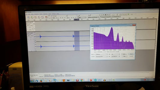
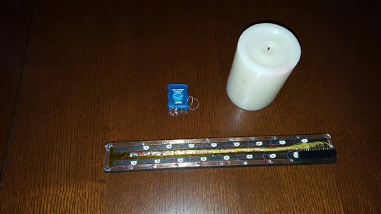
The measurement of frequency using the Audacity program involves supporting the chime at approximately its "node" points which are located at 22.4% from each end. A microphone feeds the sound into the audacity program and the tube is "struck" several times while the signal is being recorded. The program then allows you to view any section of the produced wave signal and analyze the signal by plotting its spectrum. The various peaks of the spectrum are easily read off the graph, and you quickly can determine which peak represents the first fundamental. I suspended the tubes using 6 lb test nylon fishing line. It's what I had. Heavier lines may also be suitable and possibly easier to see, but this light line had very little effect on the tubes.
Also, the test frame evolved; with the tube first being struck by a tap from a screwdriver, into a solenoid driven striker actuated by a battery and push button. This also gave me a test bed to test my solenoid system.
Step 2: About the Solenoids
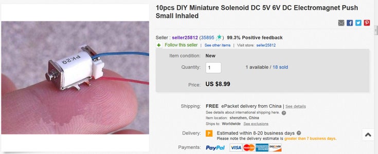

It was felt that solenoid driven strikers were the preferred method of exciting the chimes. Solenoids with spring returns were contemplated, but were too large and also too costly. I stumbled across some very small and inexpensive solenoids from a Chinese supplier on Ebay and also on Ali-Express (a Chinese supplier). They are also available from Amazon at a price of 5 for $8.00. These are very small solenoids, 5 mm in diameter and 7mm long coils. They contained a 2mm plunger and were in a magnet assembly that moved... but really not enough to be practical. See the YouTube video of my first test.
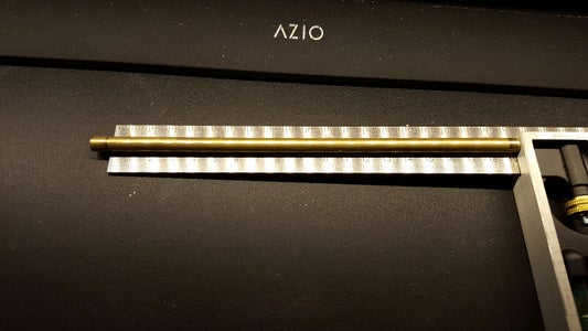
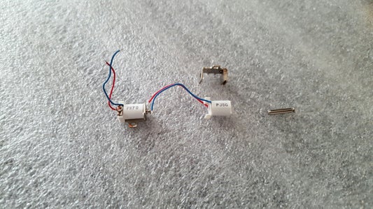
However, I decided to make a minor modification to these solenoids, and simply pried the coil from the metal housing. A 2 penny finishing nail is ,072" (1.83mm) in diameter and 1.5" (38mm) long. I cut off the point making a rod 28mm long. From Ebay I purchased some 2mm dia X 3mm long magnets ($5.00/100 pcs).
By inserting the nail into the solenoid and sticking one of these magnets on each end, I constructed a solenoid that had a very long throw and who's direction was controlled by the polarity of the supply. See the YouTube video Part 2.
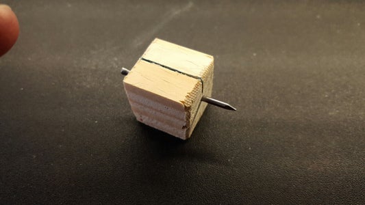
I used a Dremel (type) cut off wheel to cut the nails being careful to achieve a flat and perpendicular surface.
If the surfaces are flat, the magnets will hold themselves on the rod and no adhesive is necessary. Small pieces of shrink tubing will make the rod/magnet connection a little more durable.
Step 3: About the Electronics.

I now had the chime tubes and an inexpensive solenoid drive. I could hang the tubes vertically and mount the solenoids horizontally but that meant that I would have to either add a return spring, or actively excite the chimes to strike and then again to retract. The thought of wiring together 16 "h-bridges" was not a pleasant thought. I therefore opted for a simple "gravity return" system. Mounting the solenoids vertically allowed each to be simply "pulsed" and then they would return by their own weight. Unfortunately, this meant that the chimes had to be hung horizontally. (Various mechanisms were considered, but keeping it simple seemed the best).
Since I was going to use an Arduino, I had to determine the power requirements. The coils themselves are about 15 ohms and when excited with 5 volts, require 333 ma,... far above what the Arduino could drive directly. Also the current requirements became even greater when exciting more than one chime at a time. (I intended my chime player to have the ability to play chords as well as simple notes.)
To control each of the 16 solenoids independently sounded like the perfect application for the 74HC595 shift register. Two of these and two Arlington Driver chips (ULN2803A) could do the job and use only three Arduino pins. See the Fritzing schematic (not pretty, but gives you the idea.).
One thing a little strange about the circuit is that the driver chip uses a positive voltage for a common and when each channel is addressed , connects that channel to ground. The schematic is correct, and the circuit does work.
Step 4: Constructing the Arduino Shield
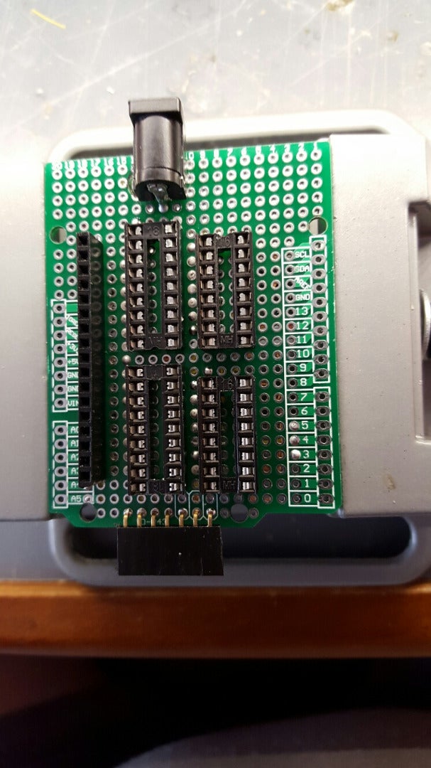


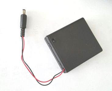


I decided build the circuit on an Arduino shield prototype board. I found a board that was all plated through holes and installed the 16 and 18 pin sockets for the ICs. I also added a 17 pin female header strip for the chime assembly input cable. A PC board power socket was added so I could use an external battery pack or power supply. This drove the Darlington drivers and also was connected to Vin pin of the Arduino. I also added another header which would accept a real time clock module for future use.
I tried to arrange the board so that additional shields could be added on top.... More on that later.
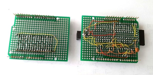
I have shown the underside view of the board wiring. Note that I reversed the orientation of the shift register and driver chips to simplify wiring. I used 30 Ga wire wrap wire, soldered (not wrapped), to complete the board.
A second shield was also constructed that powered 16 LEDs. This allows you to view the notes being played and helped in trouble shooting the software.
An interconnecting cable was made from a 20 cm long spectra cable (17 male pins on each end). The pin housings were bonded together with epoxy to make connectors on both ends of the cable.
Attachments

Step 5: The Chime Frame


I am very limited in wood working tools so I used finished wood stock available from Home Depot.
I used 3/4" X 3/4"; 1/4" X 1 1/2"; and 1/2" X 1 1/2" finished Poplar. I also used 5/16" dowel rod.
To reduce the length of the chime assembly, I spaced the tubes 15 mm apart. However, previous experience with the solenoids showed that they required at least a 20 mm spacing so their magnetic fields would not interact.
Therefore, I alternated the solenoids to make two 8 solenoid rows. This eliminated the interaction problem.
I did use an inexpensive drill stand in order to drill the holes correctly aligned. (The prototype 8 chime system was made with no drill stand and it was extremely difficult to maintain perpendicularity. )
The solenoids themselves simply press into place if you drill the right hole size. I did, very lightly file, the front of each solenoid so it was more rounded. Just a touch is required and the solenoids press into the holes with no problem. Do not install the solenoids at this point.
The frame was finished by adding the two side legs which I fastened with wood screws. I then stained the assembly before I continued.
Step 6: Wiring the Chime Player Frame

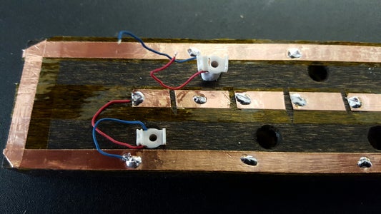
Once the pieces are stained, there are 17 connections to be made. I terminated all of them in a 17 pin header, epoxy bonded to the frame. I did use strips of copper foil to construct a common for all the solenoids, connected to pin 1 of the header. I then used small segments of copper foil to connect wiring from the header to the individual solenoid wires. The solenoid wires are very small and impossible to "strip" so I just routed them to my own terminal strips. There was a bonding problem between the copper foil and the wood base, but small touches of "super glue" were sufficient. The wiring between the header and solenoid terminals were laced with waxed dental floss to hold them "out of the way" from the solenoids.
Once the wiring was complete, the solenoid drivers can be finished.
Step 7: Installing the Striker Rods.

The frame is done. Now to install the striker rods. A simple battery circuit can be used to finish the rod assemblies. Procedure goes like this:
Connect a battery (any voltage) to the frame. Positive side to the common line.
Insert a nail in the solenoid, cut-off end down.
Add a magnet to the bottom end.
Touch the negative pole of the battery to that solenoid (not connect,,,just a touch).
If the rod moves up... you have the magnetic pole of the magnet aligned correctly; if not, flip the magnet and try again.
Once the bottom magnet is correctly oriented, a top magnet can be added on the head of the nail. It's polarity, (N/S pole), is opposite that of the bottom magnet. If correctly placed, the rod will move up. If not correctly placed, the rod will move half way (flip it and try again).
Repeat 15 more times.
After several magnets, it is actually easy to simply take a stack and add one piece of the stack to each rod.
The magnets are really quite stable as is, but to add a safe guard, I added a small piece of shrink tubing to each rod to hold the magnets in position.
You can test the assembly with the battery system. Every rod should extend when energized and fall back when not.
Step 8: The Initial Test Software
The basic system is now complete. I can add the chimes, but first.... the Arduino program.
The first program just activates each solenoid.
A 16 bit word is clocked into the two shift register chips.
Each bit of this word represents an individual chime.
The program first loads 16 "0"s into the register to initialize it.
It then sends a series of bits to activate each solenoid in turn.
The Arduino code is very simple and can be better understood with the application sketch which will be discussed later.
The good thing here is that the solenoids work as expected.
Step 9: Building the Chime Support Structure


First the chimes had to have support holes drilled. The support points should be exactly at 22.4% from each end of the tube. (Approximately is good enough). To speed the process I constructed a simple template with lines representing the tubes length and the corresponding support point location. A tube could be placed on this template, lined up with the ends touching the outer lines. The support points were marked where the tube crossed the inner lines. Then a 2 mm drill was used to drill the two holes in each tube.
You may note that the photos sometime show brass tubes rather than aluminum. This is because an additional set of chime tubes were cut from brass tubing. After all the measuring,cutting, tuning, and drilling, I decided that they were a little too heavy and might be difficult to get a good "strike" with the small forces exerted by the mini-solenoids. I then shifted to the aluminum tubes.
Two 5/16 " wooden dowels, about 3" long were inserted into the base frame. The chime frame consisted of two 1/4" X 1 1/2" wood pieces, glued to 3/4" square end pieces. 5/16" holes were drilled to mate with the wood dowels. In this way, the frame could be adjusted up or down to adjust the strike positions. Side holes were drilled and screws threaded into each end to affix the frame at the proper height. The frame was then stained to match the base
Masking tape was applied and locations of the tubes laid out. Holes were drilled at locations midway between each chime. Two holes were drilled at each location to allow nylon line to be threaded through the frame and through each tube in turn.
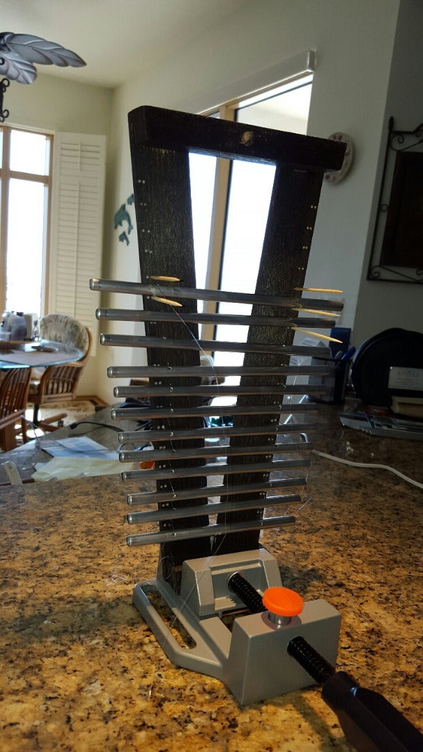
I found it easier to clamp the frame in an upright position while installing the chimes. You can cut a 3 foot long nylon line (I used 6 lb test), and thread the end through a large sewing needle. I didn't have a needle so I used a short length of steel wire to make an eye to hold the end of the nylon line.
Then the tubes were sewn on , first one side then the other. Toothpicks were used to temporarily support the tubes as they were added. Every 4 tubes or so, the frame was placed on a flat surface and the lines adjusted so the tubes would hang at the same height. After adjustment, a hot glue gun was used to cement the line to the top frame. This process was then repeated for the rest of the tubes.
If I build another version, I would slightly modify this upper frame; constructing it with (2) 3/8" dowel rods in the place of the 1/4" X 1 1/2" cross pieces. Then drilling horizontal holes would give me a cleaner support system.
There is one last piece of hardware that can be added... A cushion to muffle the sound to the strikers as the fall back. There is a noticeable "click" as the top and bottom of the striker rod hit the solenoid housing. The click is masked when the striker hits the chime, but is noticeable upon its release. A simple solution is to not allow the striker rod to completely return to the bottom. Another piece or 1/4" X 1 1/2" wood, covered by a thin sheet of plastic foam, is installed below the striker frame. This cushions the rebound and eliminates the "click".
Step 10: The Arduino Software
I have shown two Arduino sketches...
The first simply plays all the notes up and down, and then only the notes of the scale up and down.
I have tried to add enough comments to the program so it is easy to follow the logic. I have made each note an unsigned integer and declared its value in the program definitions. The definitions also allow setting the tempo, the number of beats until the next note, how long the striker should be energized, and if you wish to shift the key signature up or down by "Key" number of steps, I'm not sure how useful this is since it simply does a circular shift and cannot actually change the pitch of the note. But,..,just use zero for a value and it is ignored.
It is a challenge to find songs that can be played with only 16 notes to play with. Even a small harmonica has 20 notes. But the sounds produced by the chimes are very complex and many overtones are produced.
To illustrate what can be done, I coded one of my favorite songs by Enya... Watermark. You can hear the result in the initial video... The sketch and the sheet music are shown.
A good source for free sheet music can be found here.

Step 11: What's Next?

Probably the next addition will be the real time clock. I already have a socket in place for it to plug into the I2C bus. When not used for music, the chime player can be set to become a Chime Clock; sounding melodies on the hour or whenever. Maybe a keyboard will be added and a record feature. A switch could be used to select different songs. (There is lots of memory available). Maybe a different set of chimes tuned only to the primary scale tones would allow more song selection increasing the range over nearly 2 octaves. The hardware allows for many options by simply changing the program.... a good test of coding skills..
If I had some better wood working tools, I might have made the solenoid base into a box structure and placed all the electronics in the box. The player would then be stand alone. It would be easy to make the same circuitry using an Arduino-mini and all of the rest of the circuit on a single board. But for a first try, I was delighted with the outcome.
Step 12: Working With the Chime Player
As mentioned previously, I added a connector for a real time clock (RTC) to the circuit board..The purpose was to allow the player to assume the roll of a chime clock.
I plugged in a RTC board, pasted a few lines of code into the "Watermark" sketch, and now have something to remind me how time flies.
Sweet background music on the hour.
Please forgive the "sloppy code", I was after the destination, not the trip, this time.
Another modification... I changed the melody of the Chime Clock so that it now plays the Westminister chime sequence. It now chimes a brief note sequence on the quarter, half, third quarter. and hour. You might refer to it as "Little Ben". I left off the hourly chime count after the hour melody...


