

Introduction: Arduino Countdown Timer
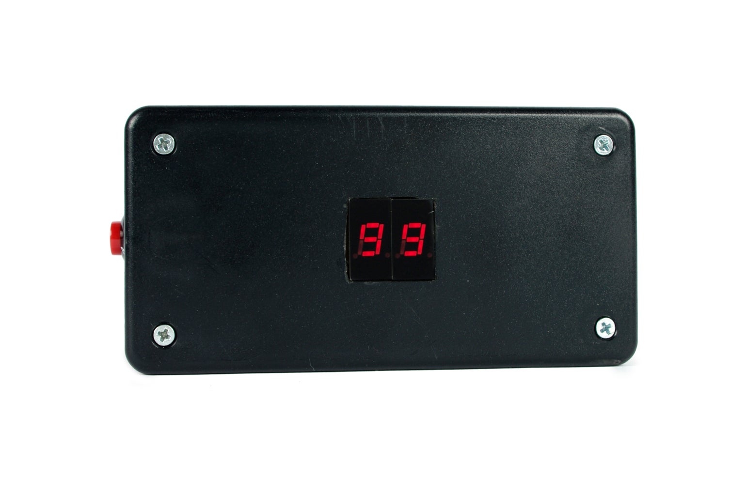


The Arduino Countdown Timer is a fun weekend project for beginners who wants to move on to something slightly more advanced. The timer controls two 7-segment displays which count down from 99 to 0, and can be stopped and started using a button. When the timer reaches 0, the display flashes and a buzzer beeps. This project is ideal for timing any life activity that happens in 99 seconds or less.
An interesting thing about this project is that the two displays collectively have 16 pins which are used, but the Arduino is able to control both using only 9 pins thanks to a technique called mulitplexing. This technique allows only one light to be on at any given time by connecting them together and then letting the Arduino control which display gets connected to ground. Even though only one light can be controlled at a time, thanks to the phenomenon of persistence of vision, if both lights are flickered on and off in series fast enough, we perceive them to both be on all the time. While this may seem complicated, this is actually a commonplace technique for controlling LED displays.
Get experimenting and see for yourself by building your own!
Step 1: Materials
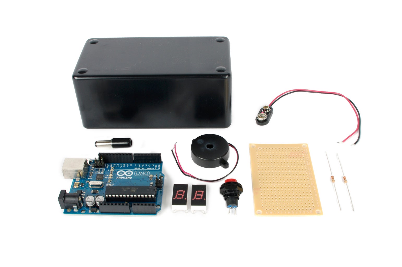
You will need:
(x1) Arduino Uno
(x2) 7-segment display
(x1) SPST momentary pushbutton switch
(x1) DC power plug
(x2) 220 ohm 1/4 watt resistor
(x1) 10K ohm 1/4 watt resistor
(x1) Grid-Style PC Board
(x1) Piezo element
(x1) 9v snap connector
(x1) 9V Battery
(x1) 5" x 2.5" x 2" project enclosure
(x1) 22 awg solid core wire
Please note that some of the links on this page contain Amazon affiliate links. This does not change the price of any of the items for sale. However, I earn a small commission if you click on any of those links and buy anything. I reinvest this money into materials and tools for future projects. If you would like an alternate suggestion for a supplier of any of the parts, please let me know.
Step 2: Attach the Display

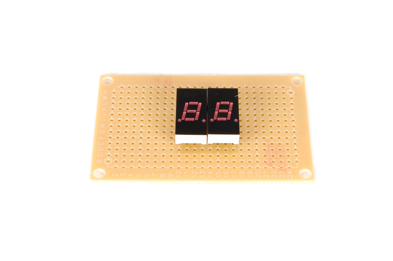

Center the two 7-segment displays side by side on the PC Board. Hold them in place by soldering each of the display's corner pins.
Step 3: Resistors
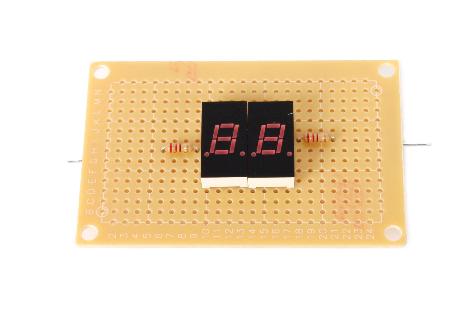

Solder a 220 ohm resistor to the common cathode pin (pin 4) on the lefthand 7-segment display, and another 220 ohm resistor to the common cathode pin (pin 12) on the righthand 7-segment diplay.
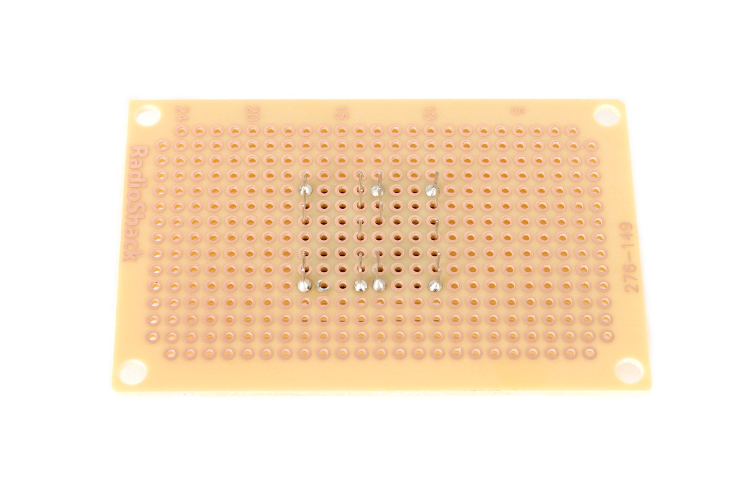
Step 4: Solder Together

Solder together all of the anode pins from one of the 7-segment displays, to the corresponding anode pins on the other 7-segment display.
For instance, pin 1 from the lefthand display should be connected to pin 1 from the righthand display. This process should be repeat for pins 2, 6, 7, 8, 13, and 14.
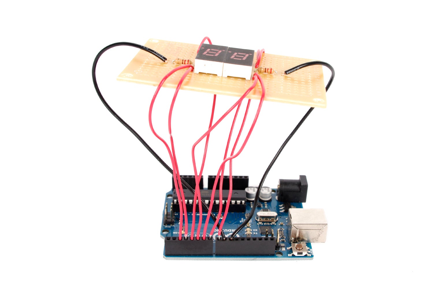
Step 5: Attach Wires

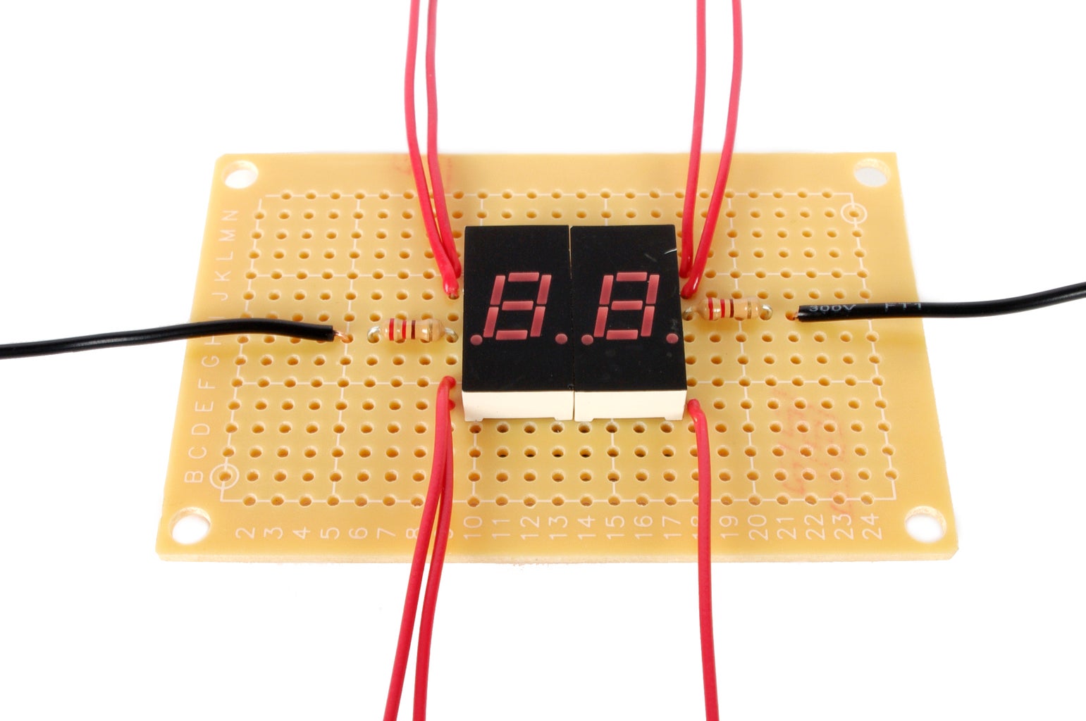
Attach a black wire to each of the end of the 220 ohm resistors not connected to the displays.
Solder a red wire to each individual pair of connected anode pins. There should be seven red wires in total.
Step 6:


Place a piece of tape over the front of the 7-segment displays. Rub over them with a pencil until a solid outline appears.
Step 7: Tape

Place the tracing centered upon the enclosure lid.
Step 8: Drill


Using a 1/8" drill bit, make holes in each of the inside corners of the tracing.
Step 9: Cut


Insert the blade of a coping saw through one of the holes in the lid and use it to cut out the square outline.
Step 10: Clean


Remove the tape and file the edges of the square until the 7 segment display fits snugly.
Step 11: Battery Plug


Twist off the casing for the M-type plug and slide it onto the battery snap connector's wires.
Solder the red wire to the center terminal of the M-type plug and the black wire to the outer barrel terminals .
Twist the casing back onto the plug.
Step 12: Drill


Drill a 1/8" pilot hole in the center of one of the 2" x 2.5" side of the enclosure.
Widen the pilot hole using a 1/2" spade bit.
Step 13: Wire


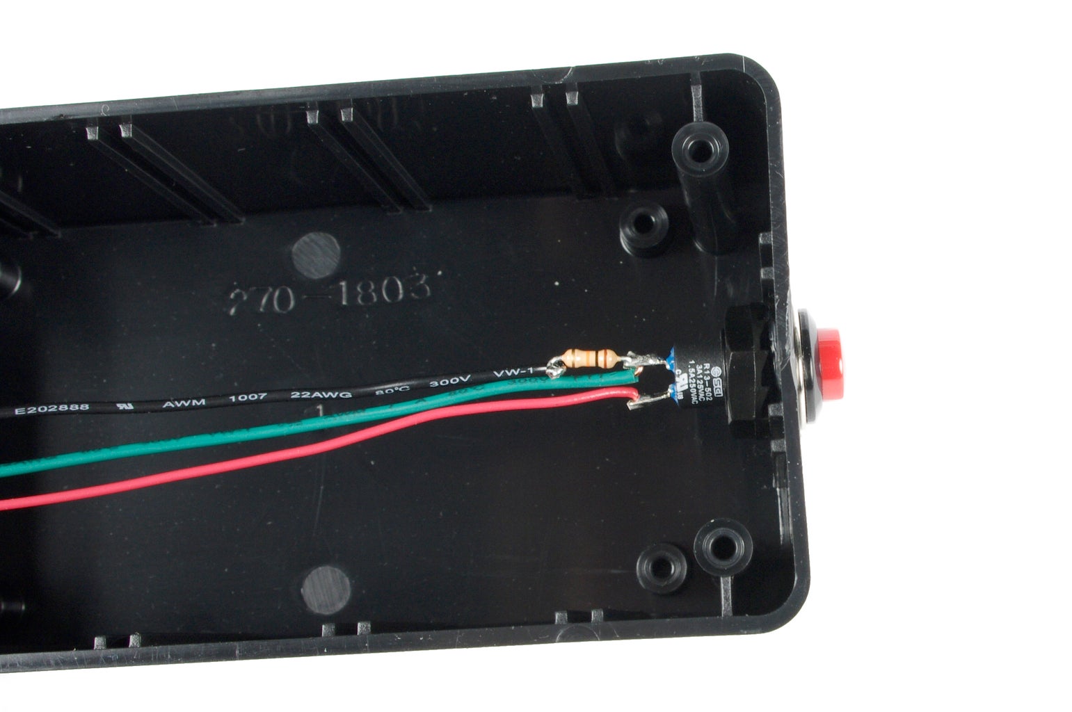
Solder a 10K ohm resistor to a 6" green wire, and then solder the other end of the resistor to one of the terminals of the pushbutton switch.
Next, solder a 6" green wire to the same terminal on the pushbutton switch as the resistor.
Finally, solder a 6" red wire to the opposite terminal of the pushbutton switch.
Step 14: Insert

Pass the pushbutton switch through the 1/2" hole in the enclosure and fasten it in place with its mounting nut.
Step 15: Program
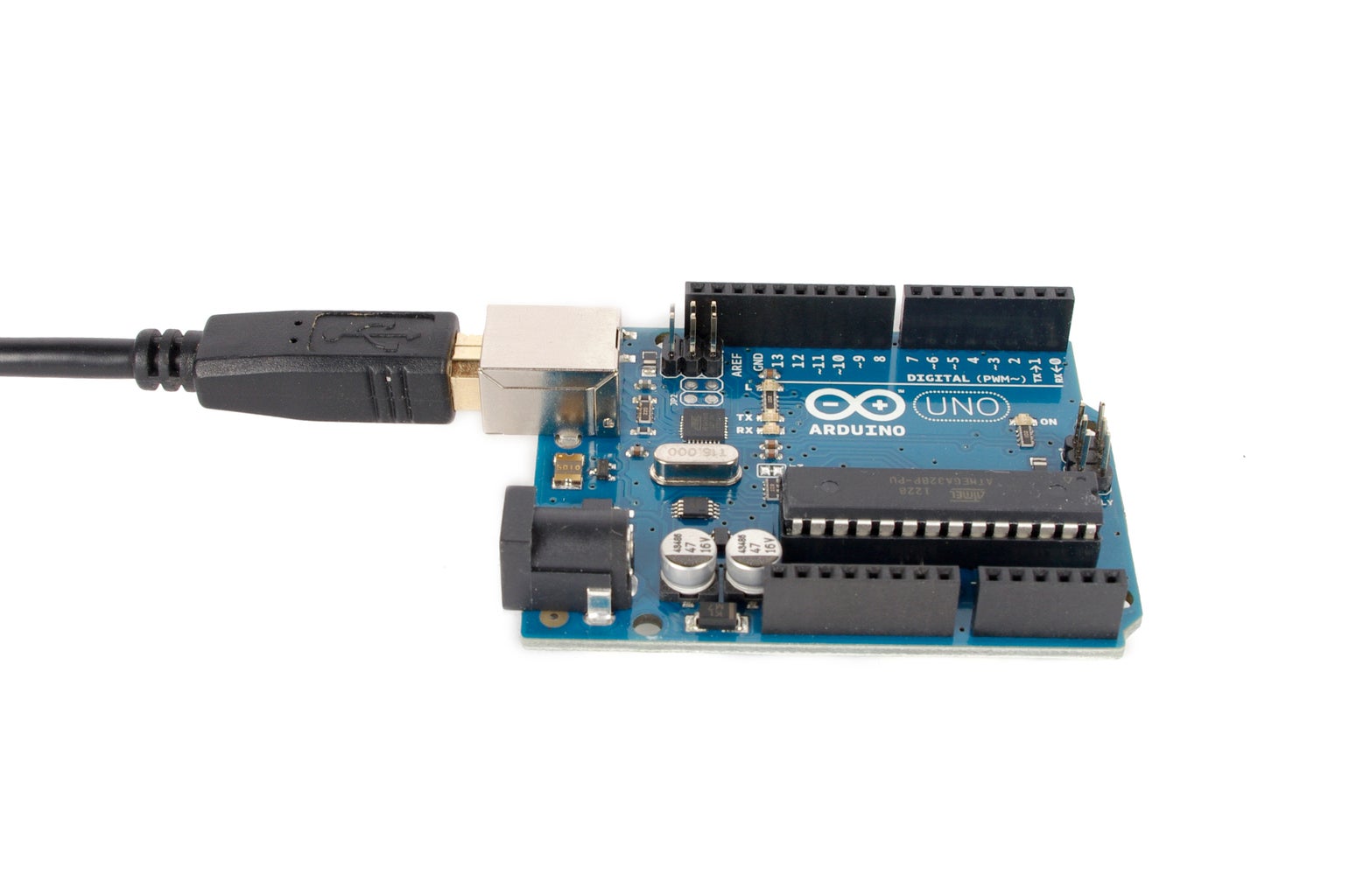
Program the Arduino with the following code:
<pre>/*

Arduino Countdown Timer
by Randy Sarafan - 2013

Uses two 7-segment displays to countdown from 99 to 0. When the timer reaches zero, the display flashes and a piezo beeps.

- To start the timer press the button.

- To pause the timer, press the button again.

- To reset before reaching 0, press the button 3 times quickly in under 1-second. When timer reaches 0, press once to reset.

For more information visit:
https://www.instructables.com/id/Arduino-Countdown-Timer/


This code incorporates Arduino State Change Detection and Debouncing example code by David A. Mellis, Limor Fried, and Tom Igoe.

This code is in the Public Domain.

*/


// The number of the pushbutton pin
const int buttonPin = 12;

// 7-segment identifier variables
int leftnumber;
int rightnumber;

// Variables for the current and the previous reading from the pushbutton pin
int buttonState;
int lastButtonState = 0;

// Additional variable to keep track of the previous button press state.
// This one only keeps track of the state of the button when there is a
// debounce delay event.
int previousState;

// Tracks the last time the output pin was toggled
long lastDebounceTime = 0;

 // The debounce time; increase if the button is registering a single press more than once
long debounceDelay = 20;

// Variable for counting the number of times the button has been pressed.
int buttonPushCounter;

// This variable gets toggled either high or low each time the button is pressed.
// In other words, this variable changes states with each button press.
bool pressed = true;


int buttonpress;

void setup() {

  // Set 7-segement outputs
  pinMode(2, OUTPUT);
  pinMode(3, OUTPUT);
  pinMode(4, OUTPUT);
  pinMode(5, OUTPUT);
  pinMode(6, OUTPUT);
  pinMode(7, OUTPUT);
  pinMode(8, OUTPUT);
  pinMode(9, OUTPUT);
  pinMode(10, OUTPUT);

  // Set buzzer output
  pinMode(11, OUTPUT);

  // Set pushbutton input
  pinMode(buttonPin, INPUT);

}

void loop() {

  for (int i = 0; i < 10; i++) {
    // Counts down the left digit by 10
    leftnumber = 9 - i;

    for (int x = 0; x < 10; x++) {
      // Counts down the right digit.
      // Since this is inside the other loop,
      // it counts down by 10 ten times
      rightnumber = 9 - x;

      // This loop displays the digits and checks the button
      // Decrease this number to make it go faster
      for (int y = 0; y < 50; y) {

        // Take a button reading
        int reading = digitalRead(buttonPin);

        // check to see if you just pressed the button
        // (i.e. the input went from LOW to HIGH),  and you've waited
        // long enough since the last press to ignore any noise:

        // If the state of the the switch has changed, due to being
        // pressed or a false contact, then reset the debounce timer
        if (reading != lastButtonState) {
          lastDebounceTime = millis();
        }

        // If the current reading is beyond the debounce delay
        // set the button state to the current reading
        if ((millis() - lastDebounceTime) > debounceDelay) {
          buttonState = reading;
        }


        // If the current state and the previous state do not match
        // and the current state indicates that the button is being pressed
        // then flip the state of the "pressed" variable (to true or false)
        // and increase the button push counter
        if (buttonState != previousState) {
          if(buttonState == 1){
            pressed = !pressed;
            buttonPushCounter++;
          }
        }

        // If the state of the button press is true
        // then the display is paused and it stops counting
        if (pressed == true){

            // Displays the left digit
            digitalWrite(9, 1);
            digitalWrite(10, 0);
            lightUpDigit(leftnumber);
            delay(10);

            // Displays the right digit
            digitalWrite(9, 0);
            digitalWrite(10, 1);
            lightUpDigit(rightnumber);
            delay(10);
          }

        // Otherwise, if the state is not true
        // the display resumes displaying the countdown
        else{
            digitalWrite(9, 1);
            digitalWrite(10, 0);
            lightUpDigit(leftnumber);
            delay(10);

            digitalWrite(9, 0);
            digitalWrite(10, 1);
            lightUpDigit(rightnumber);
            delay(10);
            y = y + 1;
          }


        // Update the previousState variable for the next loop
        previousState = buttonState;

        // Update the lastButtonState variable for the next loop
        lastButtonState = reading;

        // If both digits equal zero, stop the counter, flash 00 and beep
        while(leftnumber == 0 && rightnumber == 0){

          // Calls timesup routine and runs until the button is pressed and timer reset
          timesUp();
        }


        // If the button is pressed 3 times in under a second
        // reset the program
        if (buttonPushCounter > 2) {
          buttonPushCounter = 0;
          return;
        }
      }

      // Resets the button press count after 1 second
      buttonPushCounter = 0;
    }
  }
}


// This function runs over and over when the time runs out
// Only pressing the red button makes this stop
void timesUp(){

  // Beep on
  analogWrite(11, 20);

  // Display "00" 1/2 second
  for (int z = 0; z < 25; z++) {
    digitalWrite(9, 1);
    digitalWrite(10, 0);
    lightUpDigit(0);
    delay(10);

    digitalWrite(9, 0);
    digitalWrite(10, 1);
    lightUpDigit(0);
    delay(10);

    // Reset the counter if the button is pressed
    // and disable the display and beep
    if(digitalRead(buttonPin) == 1){
       pressed = true;
       leftnumber = 9;
       rightnumber = 9;
       analogWrite(11, 0);
       digitalWrite(9, 1);
       digitalWrite(10, 1);
       delay(2000);
       return;
     }
   }

   // Beep off
   analogWrite(11, 0);

   // Display off 1/2 second
   for (int z = 0; z < 25; z++) {

     digitalWrite(9, 1);
     digitalWrite(10, 0);
     lightUpDigit(10);
     delay(10);

     digitalWrite(9, 0);
     digitalWrite(10, 1);
     lightUpDigit(10);
     delay(10);

     // Reset the counter if the button is pressed
     if(digitalRead(buttonPin) == 1){
       pressed = true;
       leftnumber = 9;
       rightnumber = 9;
       delay(2000);
       return;
      }
   }
}


// This function has a case statement
// which sets the pins high or low,
// and displays each of the digits.

void lightUpDigit(int DisplayNumber) {

  switch (DisplayNumber){
    case 0:
    digitalWrite(2, 1);
    digitalWrite(3, 1);
    digitalWrite(4, 1);
    digitalWrite(5, 1);
    digitalWrite(6, 0);
    digitalWrite(7, 1);
    digitalWrite(8, 1);
    break;

    case 1:
    digitalWrite(2, 1);
    digitalWrite(3, 0);
    digitalWrite(4, 1);
    digitalWrite(5, 0);
    digitalWrite(6, 0);
    digitalWrite(7, 0);
    digitalWrite(8, 0);
    break;


    case 2:
    digitalWrite(2, 1);
    digitalWrite(3, 1);
    digitalWrite(4, 0);
    digitalWrite(5, 0);
    digitalWrite(6, 1);
    digitalWrite(7, 1);
    digitalWrite(8, 1);
    break;

    case 3:
    digitalWrite(2, 1);
    digitalWrite(3, 1);
    digitalWrite(4, 1);
    digitalWrite(5, 0);
    digitalWrite(6, 1);
    digitalWrite(7, 1);
    digitalWrite(8, 0);
    break;

    case 4:
    digitalWrite(2, 1);
    digitalWrite(3, 0);
    digitalWrite(4, 1);
    digitalWrite(5, 1);
    digitalWrite(6, 1);
    digitalWrite(7, 0);
    digitalWrite(8, 0);
    break;

    case 5:
    digitalWrite(2, 0);
    digitalWrite(3, 1);
    digitalWrite(4, 1);
    digitalWrite(5, 1);
    digitalWrite(6, 1);
    digitalWrite(7, 1);
    digitalWrite(8, 0);
    break;

    case 6:
    digitalWrite(2, 0);
    digitalWrite(3, 1);
    digitalWrite(4, 1);
    digitalWrite(5, 1);
    digitalWrite(6, 1);
    digitalWrite(7, 1);
    digitalWrite(8, 1);
    break;

    case 7:
    digitalWrite(2, 1);
    digitalWrite(3, 1);
    digitalWrite(4, 1);
    digitalWrite(5, 0);
    digitalWrite(6, 0);
    digitalWrite(7, 0);
    digitalWrite(8, 0);
    break;

    case 8:
    digitalWrite(2, 1);
    digitalWrite(3, 1);
    digitalWrite(4, 1);
    digitalWrite(5, 1);
    digitalWrite(6, 1);
    digitalWrite(7, 1);
    digitalWrite(8, 1);
    break;

    case 9:
    digitalWrite(2, 1);
    digitalWrite(3, 1);
    digitalWrite(4, 1);
    digitalWrite(5, 1);
    digitalWrite(6, 1);
    digitalWrite(7, 1);
    digitalWrite(8, 0);
    break;

    case 10:
    digitalWrite(2, 0);
    digitalWrite(3, 0);
    digitalWrite(4, 0);
    digitalWrite(5, 0);
    digitalWrite(6, 0);
    digitalWrite(7, 0);
    digitalWrite(8, 0);
    break;
  }
}
Step 16: Wire It Up
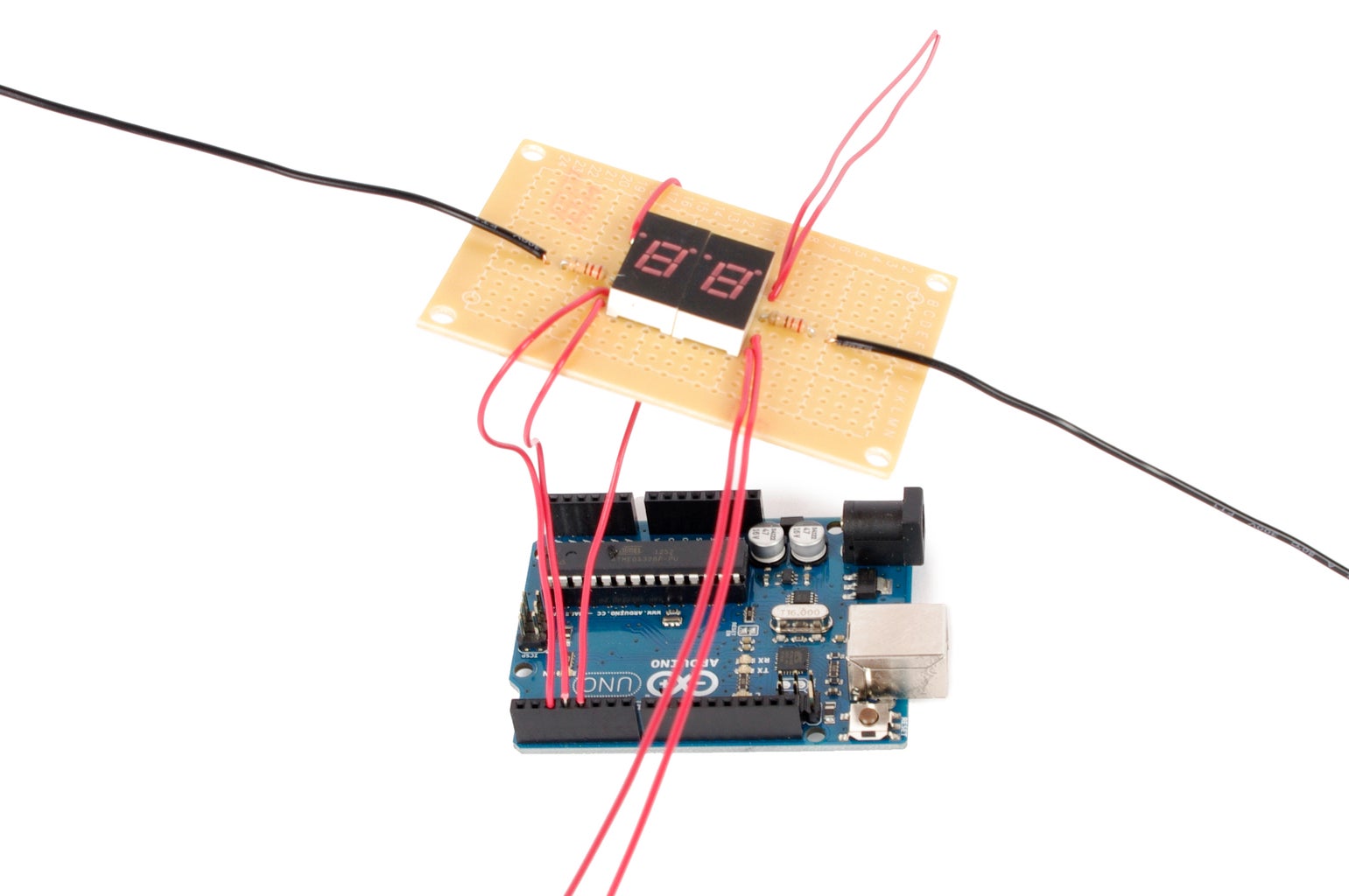
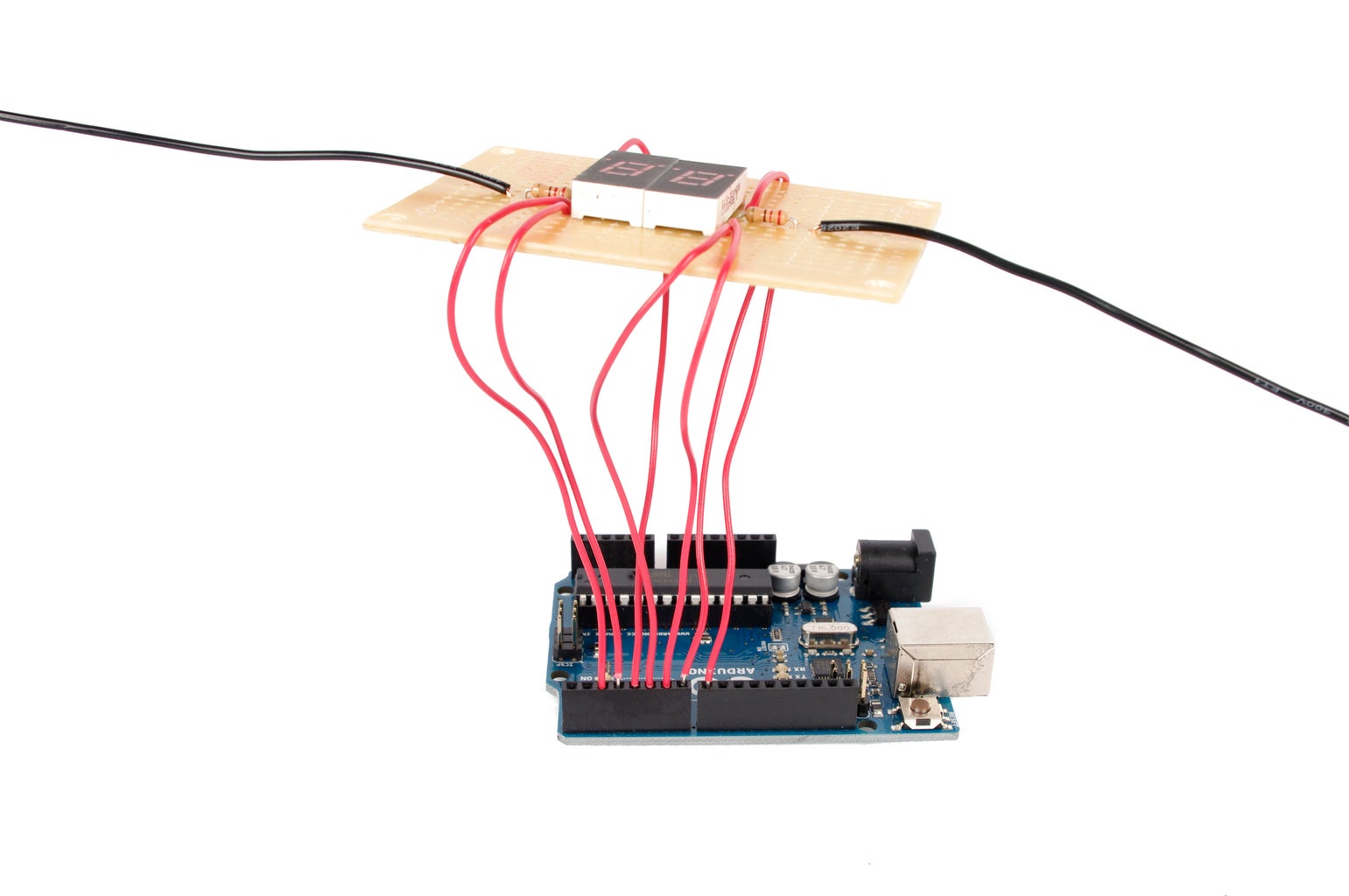
Plug the 7-segment display board into the Arduino as follows:
| 7 Segment | <---> | Arduino |
| anode pin 13 | <---> | D2 |
| anode pin 14 | <---> | D3 |
| anode pin 8 | <---> | D4 |
| anode pin 1 | <---> | D5 |
| anode pin 2 | <---> | D6 |
| anode pin 7 | <---> | D7 |
| anode pin 6 | <---> | D8 |
|
cathode pin 12 (righthand display) | <---> | D9 |
|
cathode pin 4 (lefthand display) | <---> | D10 |
Step 17: Wire the Switch
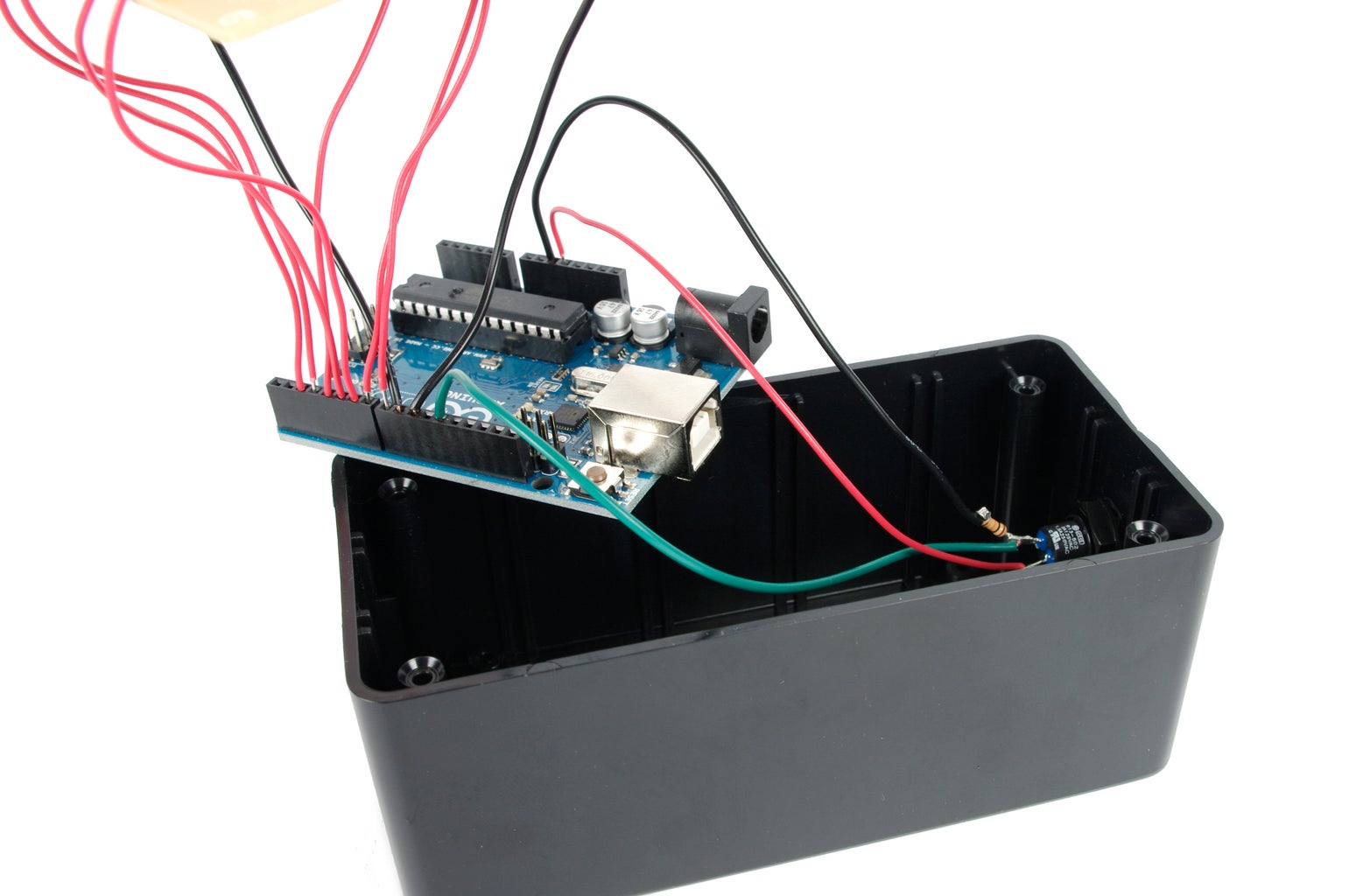
Insert the red wire from the switch into the 5V socket on the Arduino.
Insert the black wire into the ground socket on the Arduino
Connect the green wire to digital pin 12 on the Arduino.
Step 18: Wire the Alarm (optional)
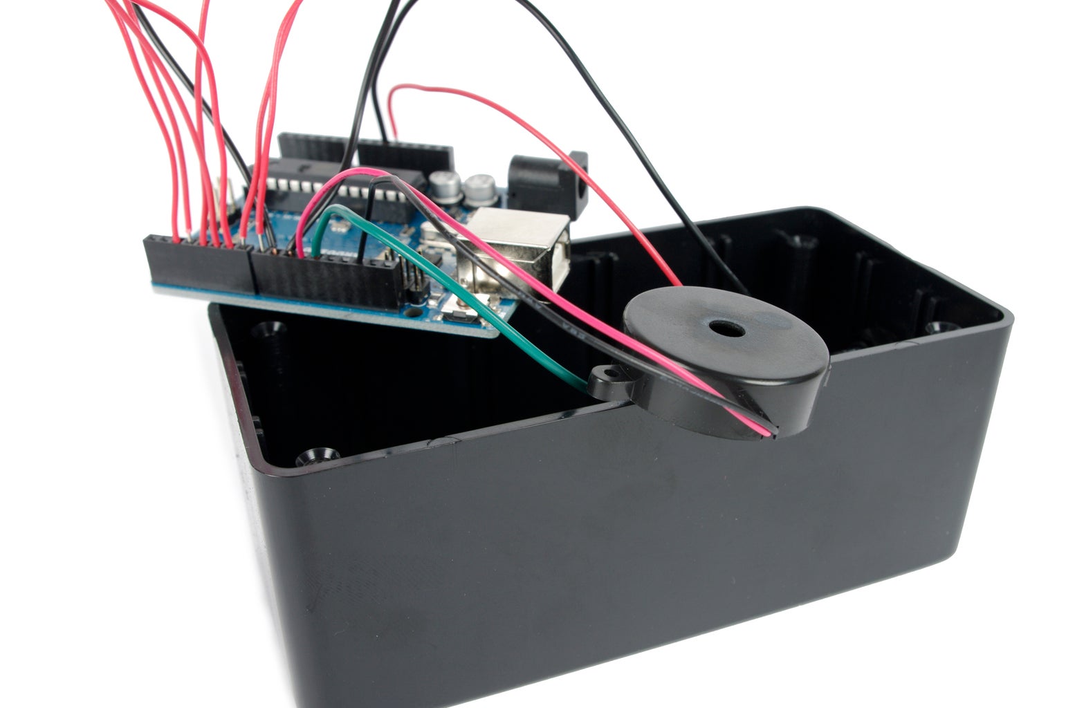
Connect the piezo's red wire to digital pin 11 on the Arduino.
Connect the piezo's black wire to one of the ground sockets on the Arduino..
Step 19: Plug In
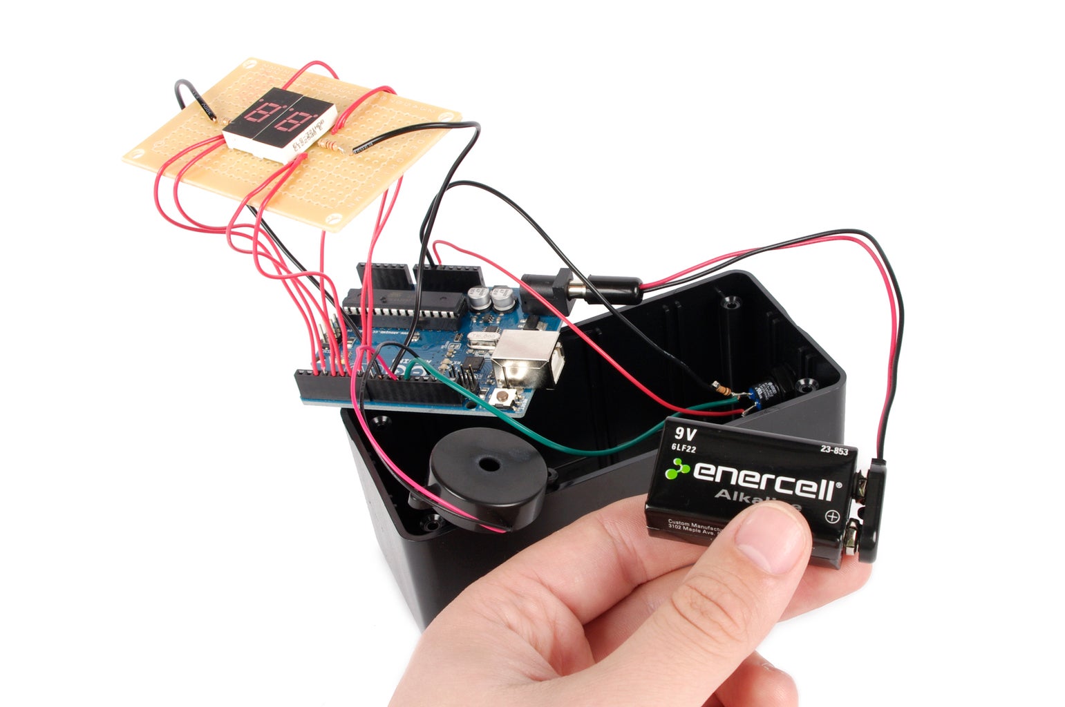


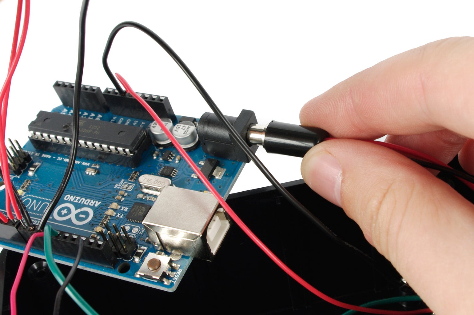
Snap together the battery connector and the 9V battery, and plug the battery into the Arduino's power socket.
Step 20: Glue
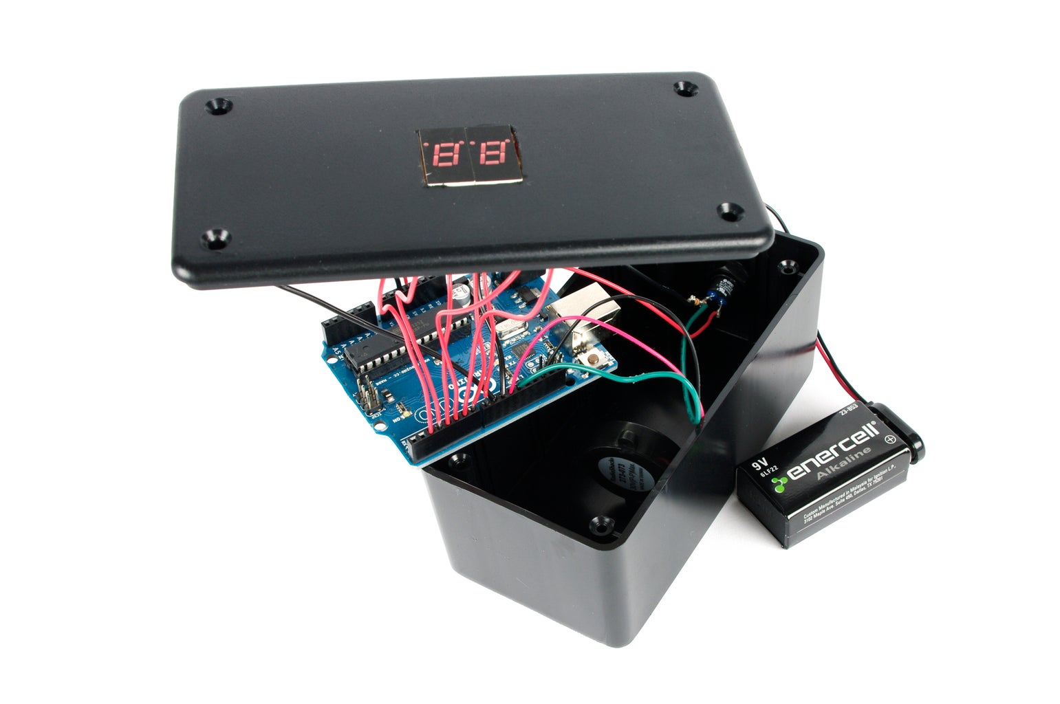
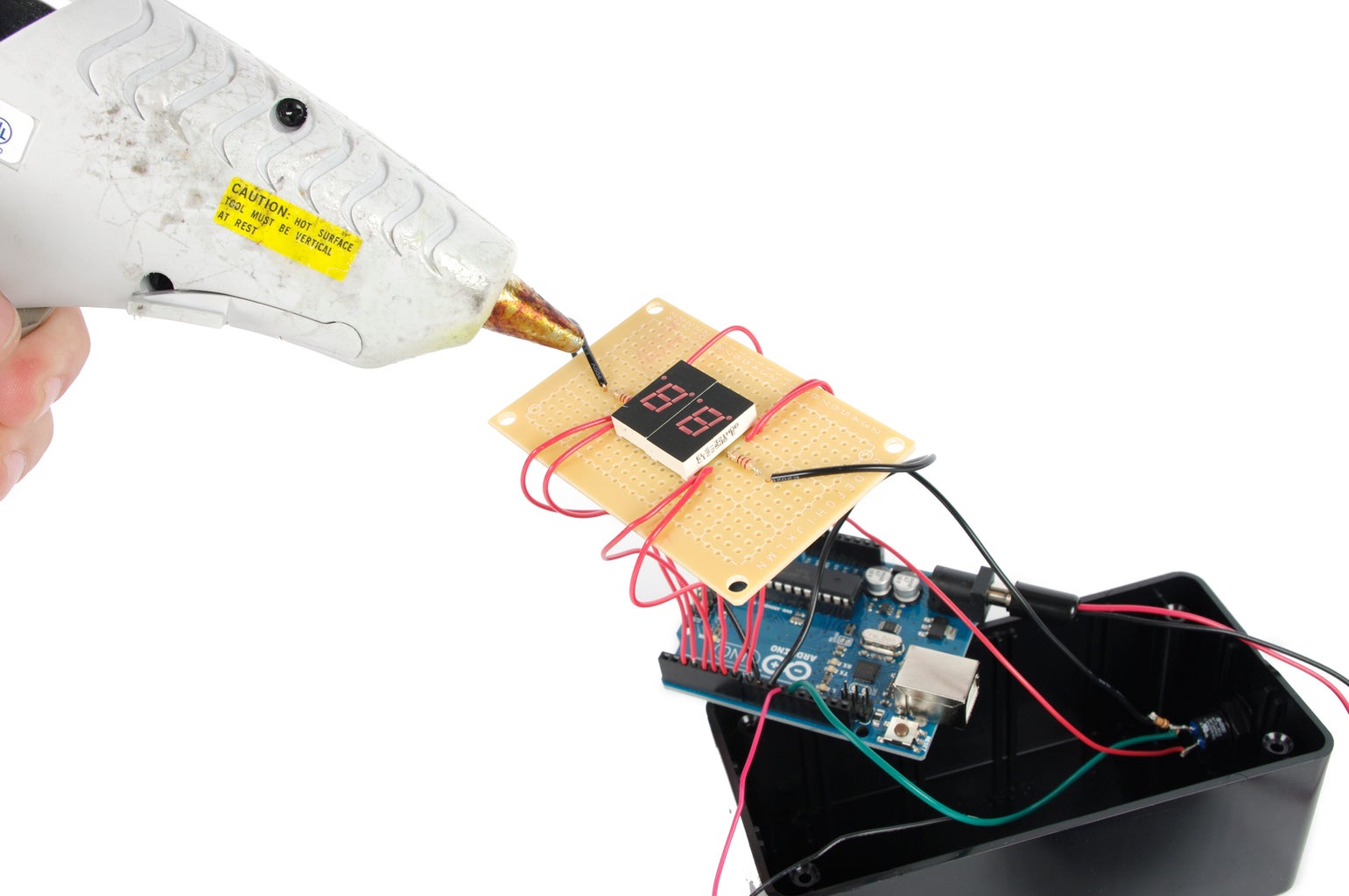

Hot glue the circuit board to the inside of the lid such that the 7-segment display is sitting snugly in the square cutout.
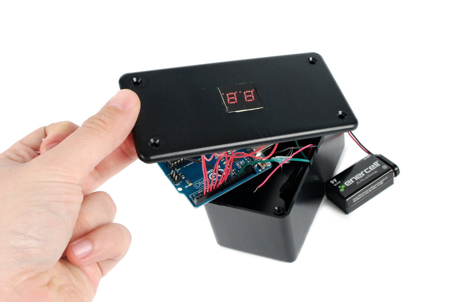
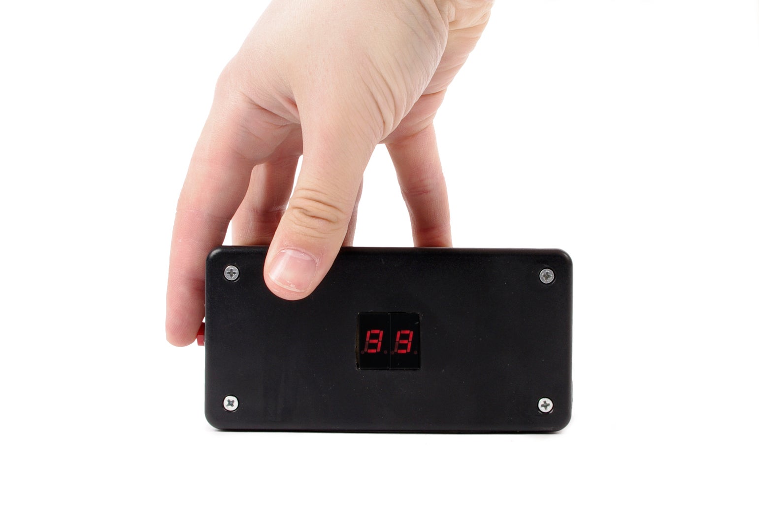
Step 21: Case Closed
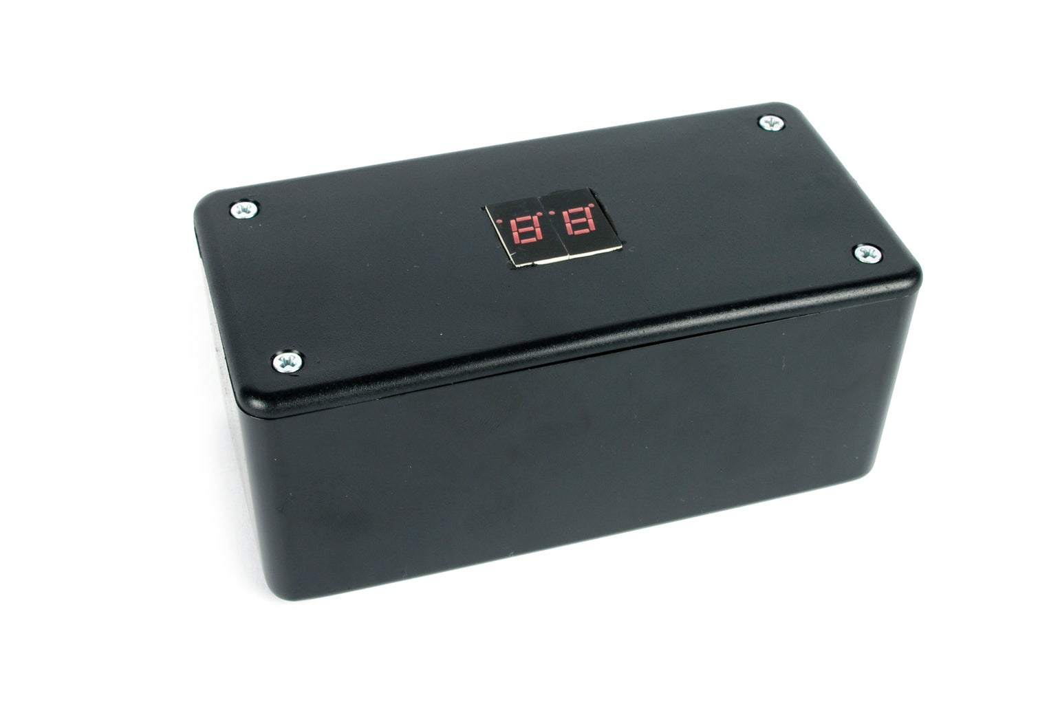

Close the lid on the enclosure and fasten it shut with the included screws.
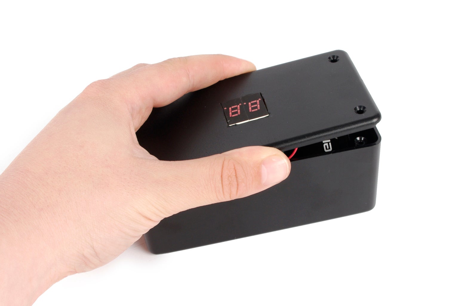
Step 22: How to Use
To start the timer, press the button once.
To pause the timer, simply press the button again.
To restart the timer, press the button 3 times quickly in less than one second.

Did you find this useful, fun, or entertaining?
Follow @madeineuphoria to see my latest projects.

Participated in the
Microcontroller Contest


