

Introduction: Arduino DMX 512 Tester and Controller ENG


Updates, files, codes, schematics ...
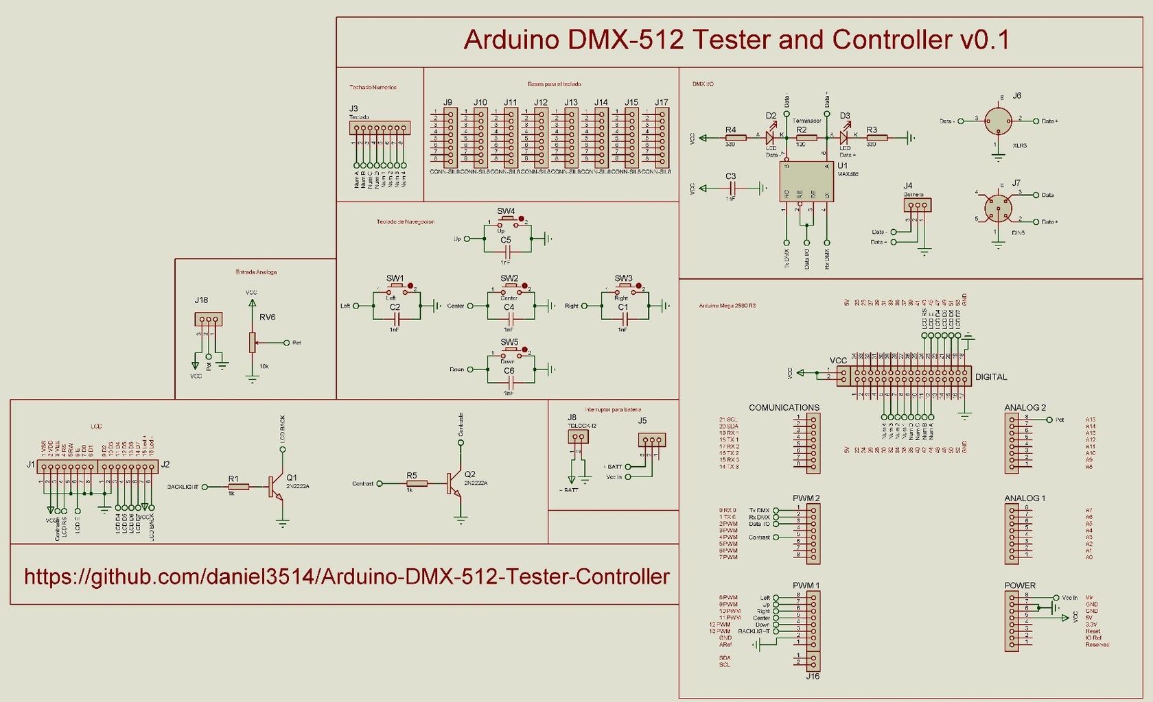
Control tool for testing and light show by the DMX-512 protocol, ideal for quick tests on fixed or temporary installations of lighting. This project arises from the need to have a portable system for rapid testing in lighting installations, without the need to install lighting consoles, interfaces or computers in environments outside, hostile or difficult to access.
Based on:
- Arduino Mega 2560 Rev-3
- Arduino library four universes DMX v0.3 - Deskontrol
- Library LCD v1.2.1 - Francisco Malpartida
- Arduino from Proteus Simulation - Microcontrolandos
Hardware v0.4
- Supports Firmware v0.9 - v1.3
- 4x20 LCD with backlight and contrast controlled by software
- Power from USB, batteries or external power supply
- Navigation keypad4x4 keypad
- Analog control potentiometer
- Switch on / off (not applicable to USB power)
- DMX output from terminal block, XLR 3-pin and 5-pin XLR
- Output status LEDs DMX
- Simulation in Proteus V7.7 SP2
- Schematic and PCB in Proteus v8.0 SP1
Firmware v1.3
- Supports Hardware v0.3 - v0.4
- Navigation from cursor easily accessible and intuitive
- Fast Inserting values from the keypad
- Insert values from analog potentiometer
- Memory Banks store 8 DMX universes
- Reading from the EEPROM to start DMX universe preselected
- Selection of memory options to start
- DMX Control Unitary, selects a specific channel, and shows the values of the previous channels and next
- Matrix Control DMX shows a 3 x 5 matrix with the values of the channels shown
- Chaser DMX Control allows sequence selected channels, with a selected time
- DMX Sequencer allows sequencing between universes stored in the EEPROM memory with a selected time
- Multiply DMX Control allows multiplying values fill the selected channels
- Function to locate luminaire from the selected channel
- Quick access to memory options
- Memory options Save, Load, Clear, Clear All (for banks and empty RAM memory)
- Memory options for the 8 DMX universes banks
- Function Black Out
- Control of LCD back light illumination
- LCD Contrast Control
- Keyboard Shortcuts from the LCD back light
- Keylight prepared for a next version of hardware
- Compiled by Arduino IDE v1.0.6
- Arduino library four universes DMX v0.3 - Deskontrol.net
- Library LCD v1.2.1 - Francisco Malpartida
Step 1: Licence

Step 2: Schematic
Step 3: PCB

We will have to print on a pre PCB negative press
Attachments

Step 4: Simulator

We must run the simulator with the hex file or .elf
Step 5: Bill of Materials
Attachments
Step 6: Preparing the Phenolic Plate

We use a phenolic plate one face time, we reinforce the copper sandpaper water, thinner circularly
Step 7: Negative PCB


With Proteus send files to print a pre-press acetate negative (there is a PDF with the file)
Step 8:


Use and method photosensitive film
We use a paper laminator film to adhere perfectly pcb
Step 9: UV Light


Add a little water between the plate and acetate so that it does not move and apply UV light
Step 10: Revealed


Apply the ferric chloride are clean and ready
Step 11: We Perforate Plates


Step 12: Soldered Components


Step 13: Stripped to the Potentiometer Guide


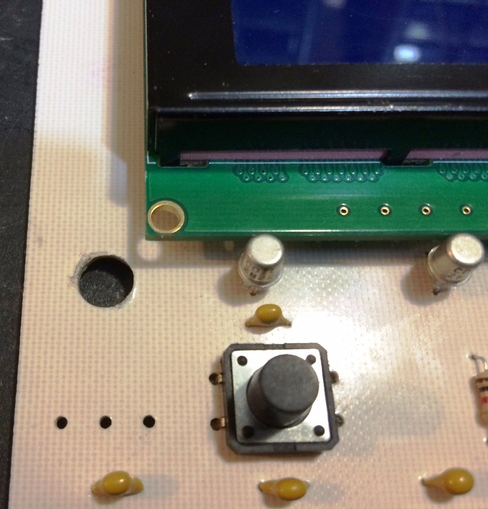


phenolic drilled plate to put the potentiometer
Step 14: Keyboard Base


In the case of the girl plate, putting them headers weld the top, above the pins cut with sandpaper and water removed the excess
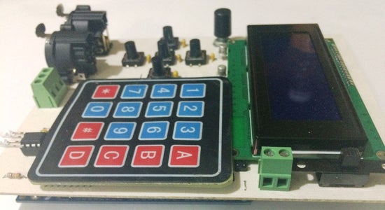
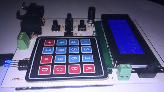
Step 15: Keyboard Mount


We add tape double tape para pegar el teclado a la placa
Here we encounter a detail, headers clogged with the flex of the keyboard, the cut (we consider for the next version)
Weld the headers that are under the keyboard and bend backward to connect the keyboard laterally
We put in place the keyboard on the LCD board, here's a detail, the base of the MAX485 am very attached to the keyboard, we force a little (we consider in the next version)
Step 16: Mount the Arduino


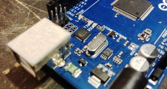


We add to Arduino Mega some tape to the USB port to prevent a short circuit between tracks
Step 17: All Welded Components


Step 18: Load the Firmware on the Arduino


Attachments
Step 19: Working ...


