

Introduction: Arduino Digital Clock (With Charlieplexing LEDs, 7 Segment Displays)


I used 4 seven segment displays to display time in 24hr format. Here ii experimented with common anode and common cathode. Now i wanted to use other chips too and not just the Arduino which would have been the easier option. The chips i experimented with are 74LS47, 74HC154, 74HC595 ,4511 and 74HC139. The final compatible combination was common cathode with 4511 and 74HC139.
I used a RTC chip DS1307 to feed the time to the Arduino. I initially wanted to use millis() function in Arduino but it is not that accurate. Using RTC not only saved long coding but also has an added advantage of keeping the time in case the external supply is cutoff. It uses a 3v battery to do this.
Now I have used LEDs to point the time as minute and hour hands would do in an anolog clock. 60 Bi-coloured LEDs total which work on Charlieplexing.
Well if you are interested onwards you go.
Step 1: Parts List

Atmega168 (Duemilanove) + Holder
CD4511BE+ Holder (CMOS BCD-TO-7-SEGMENT LATCH DECODER DRIVER)
74HC139N + Holder (Dual 2-to-4 line decoder/demultiplexer)
DS1307+ Holder (DS1307 64 x 8, Serial, I C Real-Time Clock)
7805
Standby Arduino board to Burn bootloader in Atmega168 (optional if Already hav a chip with Arduino bootloader in it)
Breakout board + USB wire
Common Anode 7 segment display (4)
16Mhz crystal
32.768 Khz watch crystal
9v battery + Plug
3v coin cell +Holder
Push button switch (Reset Arduino)
22pf ceramic capacitor (2)
100nf ceramic capacitor (3)
100uf electrolytic capacitor (2)
2.2 Kohms resistor (2)
10 Kohms resistor
5mm Bicolour LED (60) (There are different types see further for more information)
Male headers
Two Jumpers
PCB
Connecting wire
Soldering iron
Solder
2mm thick Plexiglass
Glass paint kit
Aluminium foil
3/4th inch Nut and Bolt
Hook to hang by a nail (I made one fron plexiglass pieces)
PCB drill
Glue gun
Step 2: Circuit

I have made the circuit in Eagle but sadly I am not that proficient in using the software (Which is next on my "TO LEARN" list) so I didn't make the board. I have attached the schematic i made on Eagle. U can use it to make the board.
I used Express PCB to create the PCB. I have also attached this .pcb file here. You can eitherprint this file directly and make a pcb from a copper clad or build a board from Eagle and get it made professionally.
NOTE:
1) In express PCB file I've used JMP at some places. It means you have to use wires to short the two pads. This was necessary since i used a single sided PCB. Confirm where to connect wires from the circuit diagram.
2) At digital pin 0 and 1 i have used jumpers. This is VERY IMPORTANT as the LEDS have to be disconnected from these points as they are RX and TX pins. LEDs if connected while uploading the program will use up the voltage and hinder the uploading. I learnt it the hard way. So i made changes afterwards. So while uloading Remove the jumpers thus effectively disconnecting them from LEDs and replace them once the uploading is done.


Step 3: LED Circuit


The PCB that i have built does not include the Charlieplexing LED circuitry. I made the 12 round tracks using a waterproof marker and compass.
IMPORTANT POINTS TO REMEMBER
1) The outermost track is 16cm in diameter.
2) The innermost track is about 12.5cm in diameter.
3) These diameter specifications you can vary as long as the total width of 12 concentric tracks does not exceed the length of the LED leads or you won't be able to solder properly.
4) The actual placement of the LEDs was done manually i.e without the help of computer. I found it easier and faster.
5) Do not make any hole pads for the LEDs before etching. Just be sure to make the concentric tracks thick enough so after drilling they wont get disconnected completely.
Now etch the PCB. See the Image for what it should look like.
Step 4: Charlieplexing 120 LED


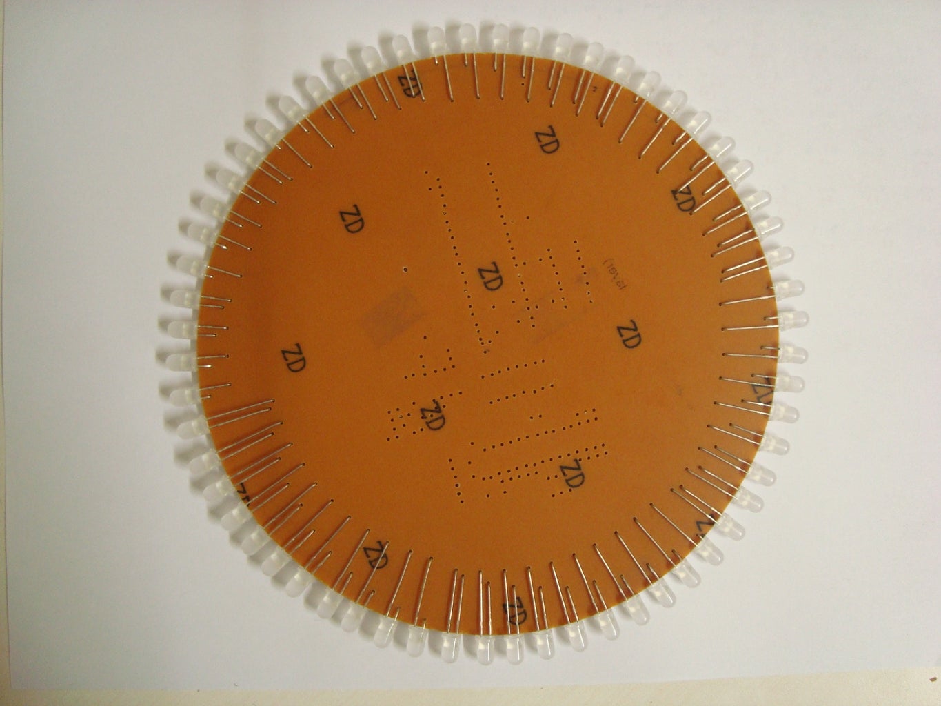
I decided to not to use LEDs to display seconds. So that means 60 LEDs for hour an 60 for minutes which round off to 120. Soldering so many would have been a pain in the ass. Luckily i stumbled upon Bi-colored LEDs with 2 and 3 pin. 2 pin ones were perfect for this application.
I learnt Charlieplexing from this site. It explained perfectly how it works.
http://pcbheaven.com/wikipages/Charlieplexing/
I needed 120 LEDs. With 12 inputs i could connect 132 LEDs in total. i Excluded 12.
Charlieplexing use two LEDs in anti-parallel connection. The Bi-colored LEDs had this inbuilt. So i used 60 such LEDs.
Now u might think connecting so many of them would be difficult. Well no. It's fairly easy.
Connect one LED from (0 to 1), (0 to 2) and so on to (0 to 11) with the positive lead to 0 for each of these 11 LEDs.(0-11 are the 12 tracks with 0 being the innermost)
Similarly (1 to 2) (1 to 3) and so on to (1 to 11).
I started with (0 to 1) at 60 minutes position (i.e at 12 hr) and went anti clockwise i.e (0 to 2) at 59th minute position.
Here are all the connections for LEDs
(0-1)(0-2)(0-3)(0-4)(0-5)(0-6)(0-7)(0-8)(0-9)(0-10)(0-11) ->11 total
(1-2)(1-3)(1-4)(1-5)(1-6)(1-7)(1-8)(1-9)(1-10)(1-11) ->10 total
(2-3)(2-4)(2-5)(2-6)(2-7)(2-8)(2-9)(2-10)(2-11) ->09 total
(3-4)(3-5)(3-6)(3-7)(3-8)(3-9)(3-10)(3-11) ->08 total
(4-5)(4-6)(4-7)(4-8)(4-9)(4-10)(4-11) ->07 total
(5-6)(5-7)(5-8)(5-9)(5-10)(5-11) ->06 total
(6-7)(6-8)(6-9)(6-10)(6-11) ->05 total
(7-8)(7-9)(7-10)(7-11) ->04 total
Step 5: Programming
If you have bought a blank Atmega168 you need to burn the Arduino bootloader in it.
Follow this link to know how.
http://arduino.cc/en/Tutorial/ArduinoToBreadboard
I successfully did it using the internal 8Mhz process.
I have used the RTC module from here
http://learn.adafruit.com/ds1307-real-time-clock-breakout-board-kit/overview
You will have to add the library so read this site information properly
Now as for the program it is attached below for you to download.
there are two versions. I like the second one. the "Chime" looks better.
The explanation is provided in the program itself.
Remember you have to upload it twice because of the RTC. Once to set the time and then comment the line to stop it resetting at every arduino reset.
Feel free to ask any questions related to the program.
Attachments
Step 6: Soldering


Cut the PCB in a perfect circle along the outer track leaving a gap of about 1mm. I got them cut from the same guy who cut the plexiglass for me.
Solder the components according to the circuit diagram.
Make the markings on the PCB to mark the minute places where the LEDs are to be soldered. I used a protractor. each minute is 6 degree apart.
From the previous step at 1st minute position will be (7-11) 2nd minute position will be (7-10). Go on soldering in reverse order.
Now connect wires from 0-11 digital pins to the concentric tracks. with Digital pin 0 to innermost track.
I've soldered two male headers on the back to apply 5v directly from an old cellphone charger. This is obviously optional.
I wanted to connect old cellphone battery and see how it works so I have made provisions to connect this battery on the back (optional). Although this was not a very good idea since the battery doesn't last very long.
If you are using a 9 volt battery to power the clock u will need a battery holder.
Step 7: Glass Painting


This is the decoration part.
I decided to use a circular Plexiglass plate 2mm in thicknessdiameter same as the PCB so that the LEDs stick out.
This was my first time glass painting and evidently i am not very good at it.
Go nuts while glass painting. Get multiple circular plexiglass plates so u can make more than one painting. You can change the front as per mood like halloween, christmas. You can even create a personal message and make it a birthday gift to some one.
Glue the bolts as seen in the pic and make holed in the PCB at their relevant position.
Cut a circular aluminium foil with same diameter as the Plexiglass and also two holes for the bolts. Be sure to cut a window in the foil for the 7 segment displays.Then glue this foil to the painting.
The purpose of the foil is to cover the circuitry which could be seen through the painting.
Fix the plexiglass to the PCB so that there is no space between Plexiglass and 7 segment displays.
I couldn't find a proper hook to hang the clock by a nail so i made one from plexiglass pieces. It didn't have to look perfect. If would not be seen anyways.
I WOULD LOVE TO HEAR FROM YOU. ANY SUGGESTIONS, CHANGES ARE WELCOME. POINT OUT THE FAULTS IF ANY I WON'T MIND. HEY! I AM LEARNING TOO. THERE IS A LOT OF ROOM FOR IMPROVEMENT. ESPECIALLY IN THE PROGRAMMING DEPARTMENT. PLEASE POST THE PICS OF THE ONE YOU HAVE MADE. I WOULD LOVE TO SEE THEM.

Participated in the
Lamps & Lighting Contest

Participated in the
UP! Contest


