

Introduction: Arduino Distance Detector With a Buzzer and LED's

This is a simple guide on how to make a distance detector using an Arduino, a HC-SRO4 Ultrasonic Sensor, a Buzzer, and some LED's. The ultimate goal of this tutorial is to use the buzzer and LED's to display how far the object is from the ultrasonic sensor.
Step 1: Materials Needed
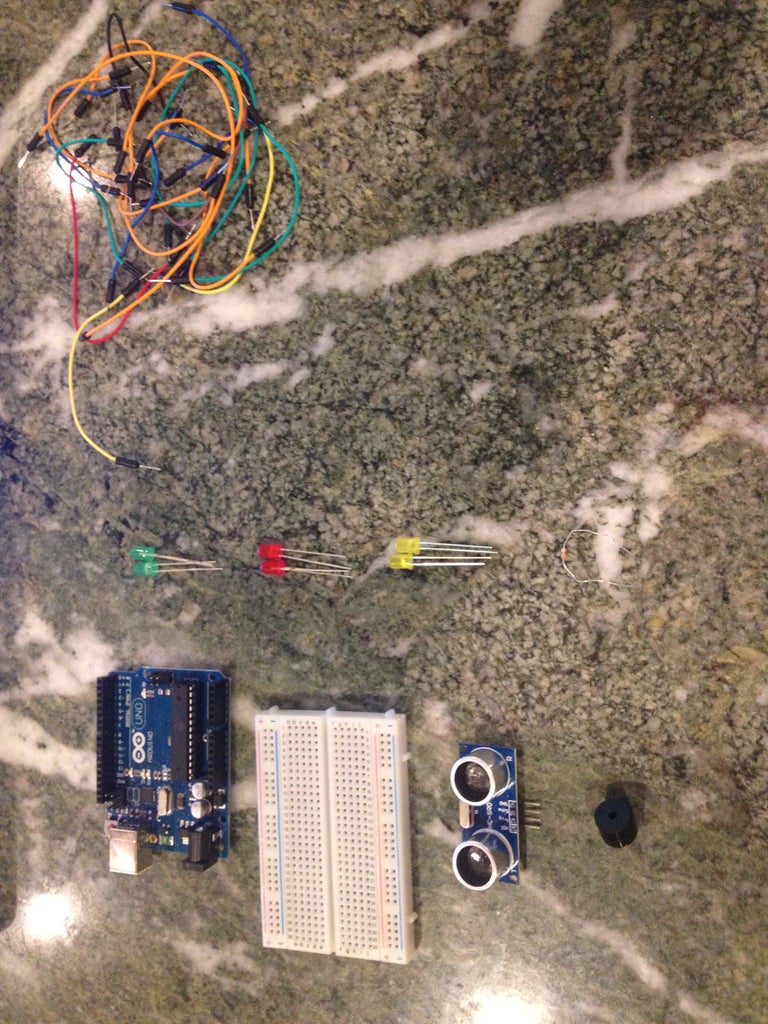
The Materials needed for this project are:
(1x) Arduino Uno
(1x) Breadboard
(1x) HC-SRO4 Ultrasonic Sensor
(1x) Buzzer
(2x) Green LEDs
(2x) Yellow LEDs
(2x) Red LEDs
(7x) 330 ohm Resistors
A lot of jumper wires
Step 2: Setup
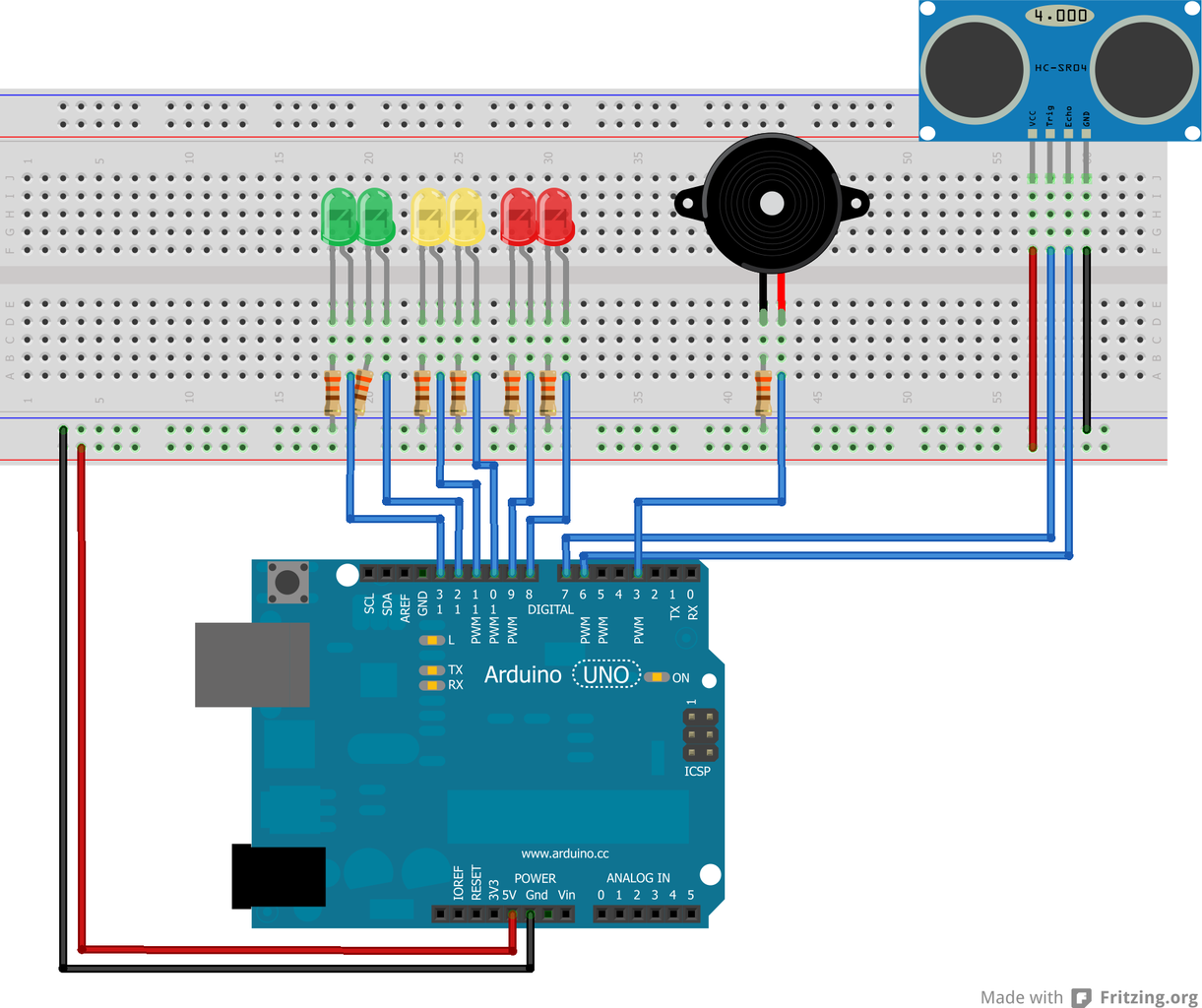
The photo above shows the setup of the project. The jumper wires should be connected as follows:
Connect a jumper wire from the 5 volt pin on the Arduino to the bottom channel of the breadboard
Connect another jumper wire from a ground pin on the arduino to the upper channel of the breadboard
Buzzer -> pin 3
(On Ultrasonic Sensor)
Echo -> pin 6
Trig -> pin 7
(In Order from Right to Left)
LED1 -> pin 8
LED2 -> pin 9
LED3 -> pin 10
LED4 -> pin 11
LED5 -> pin 12
LED6 -> pin 13
The jumper wires connected to the LEDs should be connected to the lead on the right, while the left lead of the LED should connected to the ground channel via a 330 ohm resistor.
Step 3: Assembly: Breadboard

First things first, let's connect the 5 volt and ground pin to the breadboard. Again, the wire attached to the 5 volt pin should be connected to the bottom channel of the breadboard, while the wire attached to the ground pin should be connected to the upper channel of the breadboard.
Step 4: Assembly: Ultrasonic Sensor

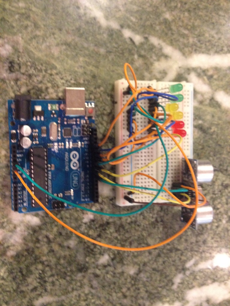
Now it's time to attach the HC-SRO4 ultrasonic sensor. It is easiest to place the ultrasonic sensor as far right to the breadboard as possible. Referring back to the setup picture, you should connect the ground pin on the ultrasonic sensor to the ground channel on the breadboard. Next connect the Echo pin on the sensor to pin 6 on the Arduino. Now connect the Trig pin on the sensor to pin 7 on the Arduino, and lastly connect the VCC pin on the sensor to the 5 volt channel on the breadboard. If you did that all correctly, your assembly should look like the picture above.
Step 5: Assembly: LEDs
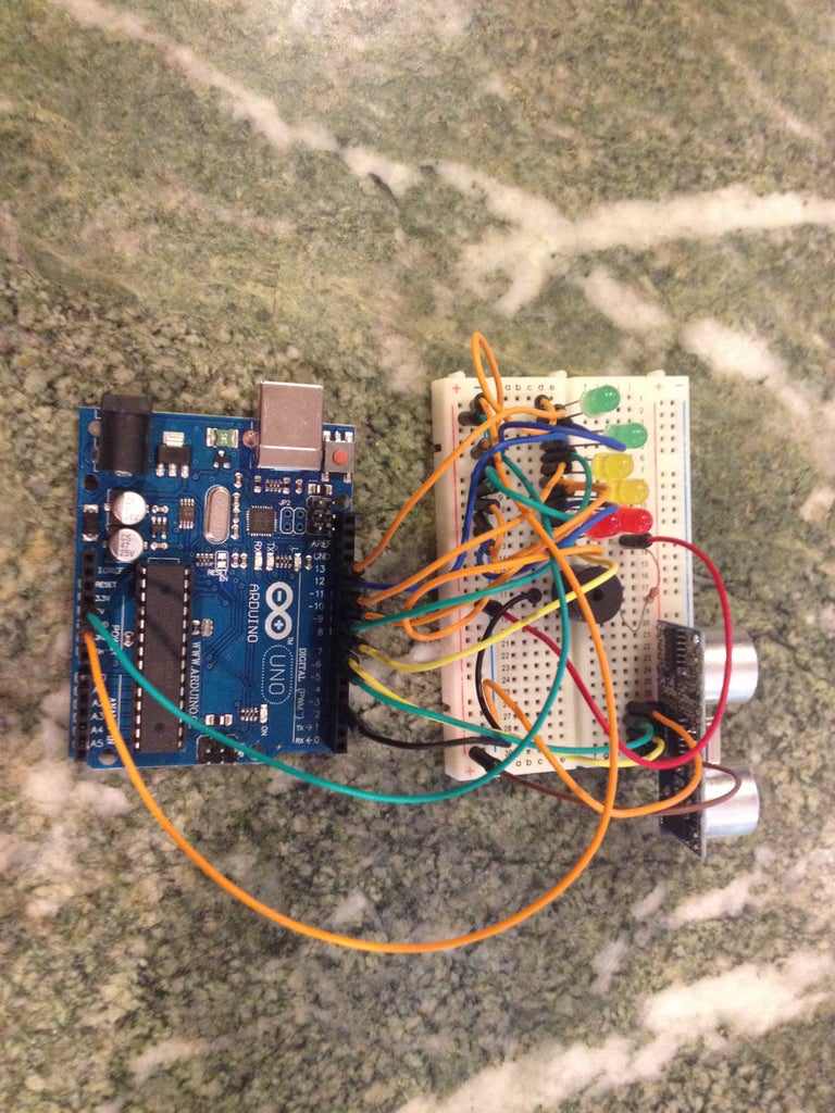
Next is connecting the LED's to the breadboard and Arduino. Once again referring back to the setup picture, attaching the LEDs is pretty basic, just with a lot of repetition. The way to connect them is to connect the anode, or the longer leg, or the one on the right, to a pin on the Arduino with a jumper wire, and to connect the cathode, or the shorter leg, or the one on the left, to the ground channel on the breadboard using a 330 ohm resistor. Then just repeat that step for all six of the LEDs, with the red LED all the way on the right being connected to pin 8 on the Arduino, the anode of the red LED to the left of that one being connected to pin 9 on the Arduino, and so on. The last LED, that being the green LED all the way on the left, should have it's anode, or right leg, connected to pin 13 on the Arduino. Once you have done that, your setup should look something like this.
*DISCLAIMER*
Resistors are not absolutely necessary for the build, however the are highly recommended to be used. The only reason I am not using them is because I don't have enough resistors.
Step 6: Assembly: Buzzer
The last part of the physical setup for this build is attaching the buzzer to the breadboard and the Arduino. This part is probably the easiest part of the setup. All you have to do is attach the longer leg of the buzzer to pin 3 of the Arduino and attach the shorter leg of the buzzer to the ground channel of the breadboard.
*DISCLAIMER*
It is HIGHLY recommended to use a resistor in connecting the shorter leg of the buzzer to the ground channel of the breadboard. This greatly reduces the volume of the buzzer. You don't have to use a resistor, but if you don't, the buzzer will be very loud and quite frankly annoying.
Step 7: The Code

Now that you have finished the physical setup of the build, now its time for the code. I assume that you already have the Arduino program on your computer, so now all you have to do is copy and paste the code from below.
#define trigPin 7
#define echoPin 6
#define led 13
#define led2 12
#define led3 11
#define led4 10
#define led5 9
#define led6 8
#define buzzer 3
int sound = 250;
void setup() {
Serial.begin (9600);
pinMode(trigPin, OUTPUT);
pinMode(echoPin, INPUT);
pinMode(led, OUTPUT);
pinMode(led2, OUTPUT);
pinMode(led3, OUTPUT);
pinMode(led4, OUTPUT);
pinMode(led5, OUTPUT);
pinMode(led6, OUTPUT);
pinMode(buzzer, OUTPUT);
}
void loop() {
long duration, distance;
digitalWrite(trigPin, LOW);
delayMicroseconds(2);
digitalWrite(trigPin, HIGH);
delayMicroseconds(10);
digitalWrite(trigPin, LOW);
duration = pulseIn(echoPin, HIGH);
distance = (duration/2) / 29.1;
if (distance <= 30) {
digitalWrite(led, HIGH);
sound = 250;
}
else {
digitalWrite(led,LOW);
}
if (distance < 25) {
digitalWrite(led2, HIGH);
sound = 260;
}
else {
digitalWrite(led2, LOW);
}
if (distance < 20) {
digitalWrite(led3, HIGH);
sound = 270;
}
else {
digitalWrite(led3, LOW);
}
if (distance < 15) {
digitalWrite(led4, HIGH);
sound = 280;
}
else {
digitalWrite(led4,LOW);
}
if (distance < 10) {
digitalWrite(led5, HIGH);
sound = 290;
}
else {
digitalWrite(led5,LOW);
}
if (distance < 5) {
digitalWrite(led6, HIGH);
sound = 300;
}
else {
digitalWrite(led6,LOW);
}
if (distance > 30 || distance <= 0){
Serial.println("Out of range");
noTone(buzzer);
}
else {
Serial.print(distance);
Serial.println(" cm");
tone(buzzer, sound);
}
delay(500);
}
Once you've done that, and you've plugged in your Arduino to your computer, run the code and you're finished. If you've followed all the directions, the closer you're hand gets to the HC-SRO4, the LEDs should progressively light up until and the closer your hand gets, the buzzer will produce a higher tone each time. If you have any questions, feel free to email me at datruckk@gmail.com.

Participated in the
Arduino Contest


